Week - 4
QUESTION 1:
AIM:
Implement control logic of a “washing machine” using Stateflow
OBJECTIVE:
- If the power supply is available, the system gets activated
- If the Water supply is not available, stop the process & indicate through LED
- Soaking time should be 200s followed by Washing time of 100s.
- Then rinsing happens for next 20s & dryer runs for 50s
- After all the processes have completed turn on the finished LED
THEORY:
A washing machine is a home appliance used to wash laundry. The term is mostly applied to machines that use water as opposed to dry cleaning (which uses alternative cleaning fluids and is performed by specialist businesses) or ultrasonic cleaners. The user adds laundry detergent, which is sold in liquid or powder form, to the wash water.
The basic requirement of the machine to run is power and water supply. After that it perform the predefined process such as soaking, washing, rinsing, drying and many other.

SIMULINK MODEL:
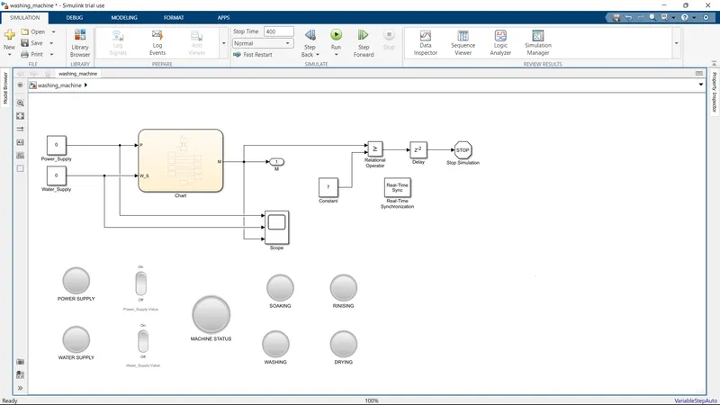
SIMULINK MODEL LINK
Click here to see the Simulink model of washing machine
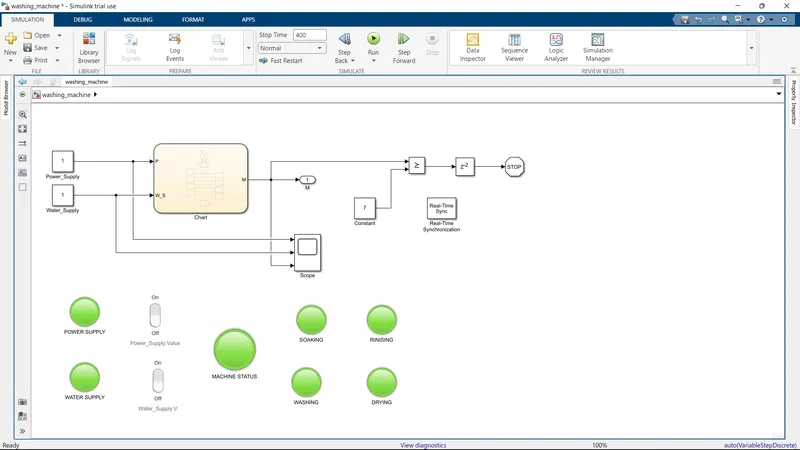
The above simulation model for washing machine.
Simulink Blocks:
- Constant
- State flowchart
- Out port
- Scope
- Relational Operator
- Delay
- Stop simulation
- Rocker switch
- Lamp
- Real-Time Synchronization
WORKING:
- Based on the given objective we need two inputs and one output to complete the control logic.
- The input signals are power & water supply and the output signal is required to show the machine status.
- Using two constant blocks we going to control the power supply & water supply inputs as 0 and 1 by connecting the rocker switch to the constant blocks.
- Then for the machine to work according to the control logic we use the state flowchart block.
- We built the control logic based on the given objective.
- Now depending upon the inputs, control logic takes transition from one state to another.
The control logic is created and shown below.
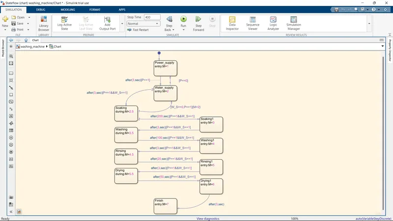
Control Logic working sequence.
- First, we check the input of the power and display the signal according to it.
- Then after 3 seconds we going to check the water supply and the display the signal according to it.
- If any one of the supplies stop in-between the process, the machine stops the process. So continuously check the power and water supply condition.
- After getting the water supply for 3 seconds we make a transition to the state of soaking.
- After 200 seconds the soaking process will complete, it now moves to the washing process state with 3 seconds delay.
- Then the washing process will complete after 100 seconds. With a 3 seconds delay, it moves to rinsing process state.
- As per the objective the rinsing is for 20 seconds, then moves to the next state called drying process with a 3 seconds delay.
- After 50 seconds drying process will complete and moves to the finish state.
- From the control logic state flowchart, we get the machine status as output.
- According to the output we display the machine status in the dashboard.
- In the dashboard we connect the lamps as follows.
- Two lamps connected to the input constant block and the conditions are given.
- And five lamps are connected to the output port the visualize the machine status.
- In those five lamps, four lamp shows the current status of process. And one is to show the overall machine status.
- After finishing the complete process, we check it using the relational operator and then stop the simulation with 3 seconds delay.
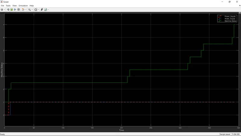
- In the scope we the record the machine status and time.
- At last Real-Time Synchronization block is used to show the simulation in real time.
OUTPUT:
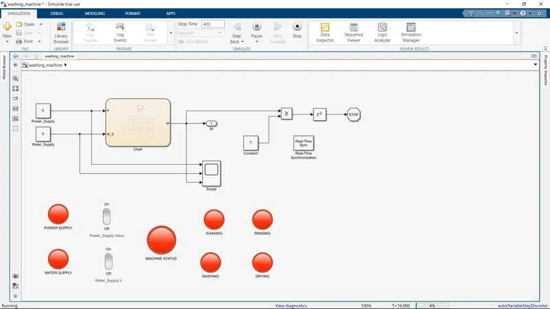
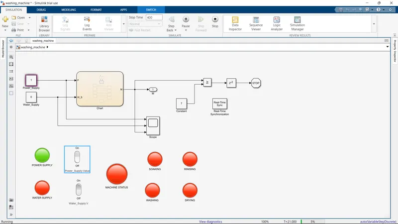
Following are the results of simulation sequence with time.
1. INITIAL STAGE
2. POWER SUPPLY
3. WATER SUPPLY
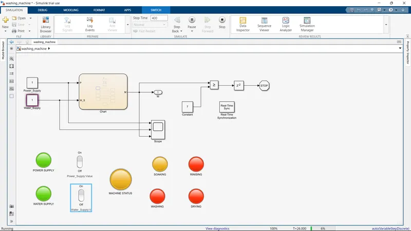
4. SOAKING PROCESS
5. WASHING PROCESS
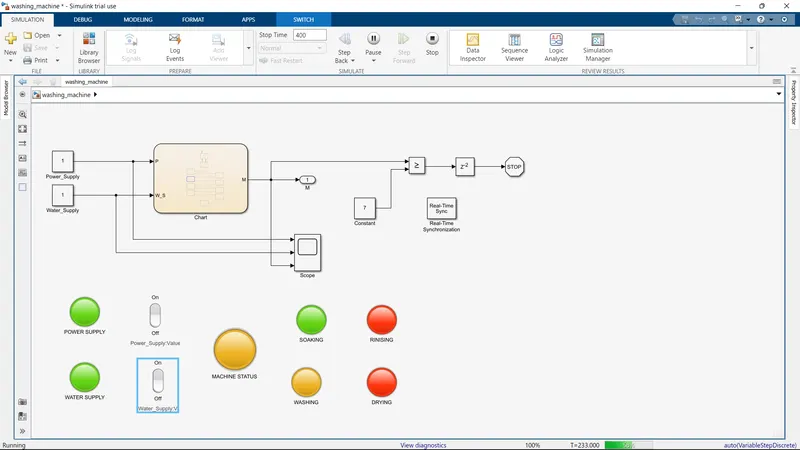
6. RINSING PROCESS
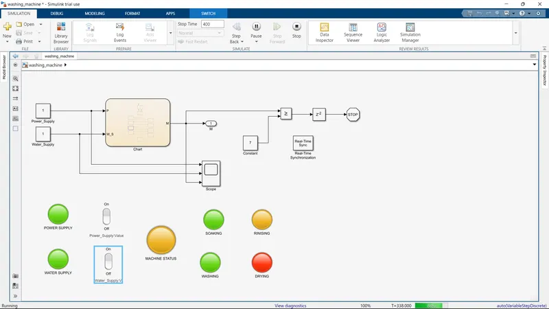
7. DRYING PROCESS
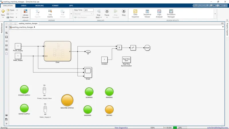
8. FINISH STAGE
SCOPE
The following link is the video of the washing machine.
Click here to see the simulation video for washing machine
QUESTION 2:
AIM:
Make a Simulink chart for the “Gear shift” logic
OBJECTIVE:
Speed Range(kmph) Gear
0 to 15 1
16 to 25 2
26 to 40 3
41 to 60 4
Above 61 5
Give speed input while the simulation is running & display the gear number.
THEORY:
A manual transmission (MT), also known as manual gearbox, standard transmission, where gear changes require the driver to manually select the gears by operating a gear stick and clutch (which is usually a foot pedal for cars or a hand lever for motorcycles).
The term 5-speed transmission refers simply to the gearbox, that uses gears and gear trains to provide speed and torque block conversions from a rotating power source to another device. The most common use is in motor vehicles, where the transmission adapts the output of the internal combustion engine to the drive wheels.
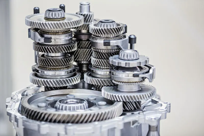
5 Speed gear box
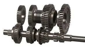
MODEL:
SIMULINK MODEL LINK:
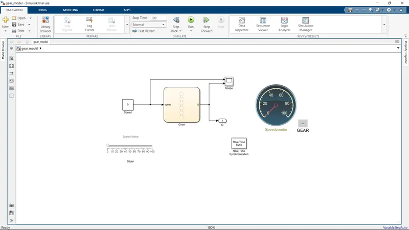
Click here to see the Simulink model of gear shift
The above simulation model for Gear shift.
Simulink Blocks:
- Constant
- Slider
- State flowchart
- out port
- Scope
- Circular gauge
- Display
- Real time Synchronization
WORKING:
- The model is just a simple program of arithmetic equation.
- We have 5 speed and 5 gear system.
- According to the given objective, we have built the control logic where it check the speed and change the gear accordingly.
The state flowchart is given below.
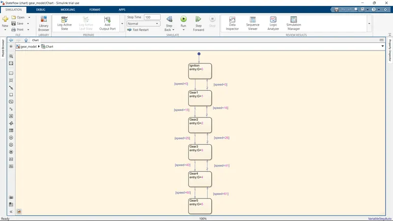
- Here we the input as speed while the simulation is running, the state flowchart run the control logic and change the gear accordingly.
- The basic concept of the control logic is checking the speed and change the gear.
- We get the output signal as gear status in G.
- In the simulation we use the circular gauge to show the input speed value. And the display shows the gear status which connect to the chart output port.
- Using the slider, we can vary the speed while running the simulation.
- We record the input speed and output gear status in the scope block.
- At last Real-Time Synchronization block is used to show the simulation in real time.
OUTPUT:
SCOPE
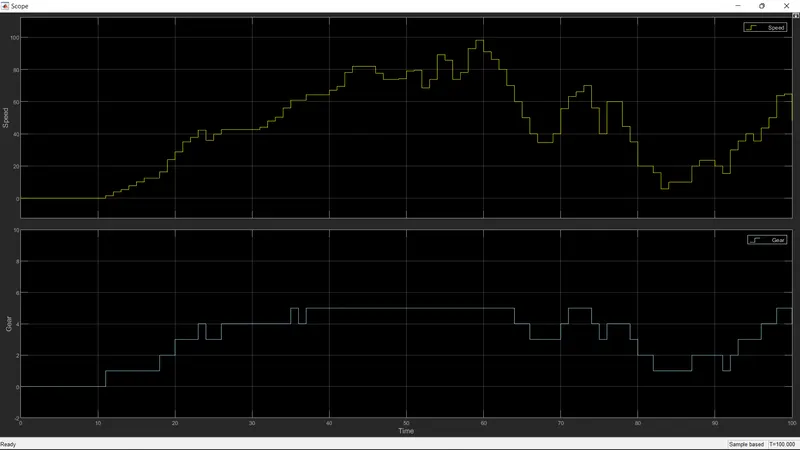
The following link is the video of the Gear shift
Click here to see the simulation of the gear shift model
REFERENCE: