Air standard Cycle - Otto Cycle
Program to solve the otto cycle
Function program
function [volume_trace] = engine_kinematics(bore,stroke,con_rod,cr,start_crank,end_crank)

% find the values of terms using in the program
%crank pin radius
a = stroke / 2;
% R is the ratio of connecting rod and crank pin radius
R = con_rod / a;
% find the volume swept by the piston in  the cylinder
v_swept = pi/4*bore^2*stroke;
% find the volume remains above the piston when it reaches TDC
v_clearance = v_swept/(cr-1);

% angle made by connecting rod
theta = linspace(start_crank,end_crank,100);

% Define the term used to find the volume trace inside the cylinder
term_1 = 0.5 * (cr - 1);
term_2 = R + 1 - cosd(theta);
term_3 = (R^2 - sind(theta).^2).^0.5;

volume_trace = (1 + term_1*(term_2-term_3)).*v_clearance;

end
Main program
% Program to solve otto cycle to plot the pv diagram
% And output the thermal efficiency

clear all
close all
clc

% Engine geomentry
bore    = 0.1;
stroke  = 0.1;
con_rod = 0.15;
cr      = 15;

% Inputs
pressure_1  = 101325;   % pascal
temp_1      = 500;     % kelvin
temp_3      = 2500;     % kelvin
gamma       = 1.4;      % no unit

% calculate the swept volume, clearance volume & volume 1
v_swept = (pi/4) * bore^2 * stroke;
v_clearance = v_swept / (cr-1);
volume_1 = v_swept + v_clearance;

% at state point 2
volume_2 = v_clearance;

% p1v1^gamma = p2v2^gamma (isentropic compression process)
pressure_2 = pressure_1 * (volume_1/volume_2)^gamma;

% p1v1/t1 = p2v2/t2
temp_2 = (pressure_2 * volume_2 * temp_1) / (pressure_1 * volume_1);

% to find v_compression & p_compression
% p2v2^gamma = constant
constant_c = pressure_2 * volume_2^gamma;
v_compression = engine_kinematics(bore,stroke,con_rod,cr,180,0); % piston moves from BDC to TDC
p_compression = constant_c./ v_compression.^gamma;

% at state point 3 (constant volume heat addition process)
volume_3 = volume_2;

% p3v3/t3 = p2v2/t2;
pressure_3 = (pressure_2 * temp_3) / temp_2;

% to find v_expansion & p_expansion
% p3v3^gamma = constant
constant_c = pressure_3 * volume_3^gamma;
v_expansion = engine_kinematics(bore,stroke,con_rod,cr,0,180); % piston moves from TDC to BDC
p_expansion = constant_c./ v_expansion.^gamma;

% at state point 4 (constant volume heat rejection process)
volume_4 = volume_1;

% p3v3^gamma = p4v4^gamma
pressure_4 = pressure_3 * (volume_3/volume_4)^gamma;

% plot the point
figure(1)
hold on
plot(volume_1,pressure_1,'*','color','r')
plot(v_compression,p_compression,'color','b')
plot(volume_2,pressure_2,'*','color','r')
plot([volume_2 volume_3],[pressure_2 pressure_3],'color','g')
plot(volume_3,pressure_3,'*','color','r')
plot(v_expansion,p_expansion,'color','m')
plot(volume_4,pressure_4,'*','color','r')
plot([volume_4 volume_1],[pressure_4 pressure_1],'color','yellow')

%label
text(volume_1,pressure_1,'1')
text(volume_2,pressure_2,'2')
text(volume_3,pressure_3,'3')
text(volume_4,pressure_4,'4')
xlabel('volume')
ylabel('pressure')
title('Otto cycle PV diagram')

% thermal efficiency
thermal_eff = (1-(1/(cr^(gamma-1))));
thermal_eff = thermal_eff*100
Step wise explanation of engine kinematics function code
Line 1 Declare the function name, inputs and output.
Line 5 calculating the crank pin radius.
Line 7 Find the value for R (the ratio of connecting rod and crank pin radius).
Line 9 Calculate the swept volume of the cylinder (maximum volume cover by the piston in the cylinder).
Line 11 Calculate the clearance volume of the cylinder (volume remains above the piston when it reaches the TDC).
Line 14 Using “linspace” command assign the array of values for theta.
Line 17 to 19 Splitting the terms in the volume trace equation. For neat presentation of code.
Line 21 Calculate the volume trace by using the equation.
Line 23 Use the end keyword to end the function. Finally save the program in the function name. To identify the function while calling the function.
Step wise explanation of Otto cycle main program code
Line 1 ‘clear all’ It clear all the memory of the temporary variable and clear the workspace.
Line 2 ‘close all’ It closes all the plots.
Line 3 ‘clc’ It clear the command window.
Line 9 to 12 Assigning the values for the engine geometry variables such as bore, stroke, connecting rod(con_rod), compression ratio(cr).
Line 15 to 18 Assign the input values for intake atmospheric pressure(pressure_1), intake atmospheric temperature(temp_1), temperature at power stroke(temp_3) and gamma.
Line 21 & 22 Calculate the Swept and clearance volume of the cylinder respectively.
Line 23 Calculating the initial volume of the cylinder(volume_1).
Line 26 Calculate the volume at state point 2(volume_2).
Line 29 Find the pressure at state point 2 by using the( pv^gamma ) because isentropic compression process.
Line 32 Calculate the temperature at state point 2 (p1v1/t1 = p2v2/t2).
Line 36 Find the value for the constant.
Line 37 Calculate the value for volume during compression by calling the engine kinematics function and give the input variable along with the angle made by the piston during compression process from BDC to TDC.
Line 38 Calculate the pressure during compression process by using the relation (pv^gamma = constant).
Line 41 Calculate the volume at state point 3. The volume at state point 2 and state point 3 are equal because it is a constant volume heat addition process. There will be no volume change.
Line 44 Calculate the pressure at state point 3 by using the relation (p3v3/t3 = p2v2/t2).
Line 48 Find the value for the constant.
Line 49 Calculate the value for volume during expansion by calling the engine kinematics function and give the input variable along with the angle made by the piston during compression process from TDC to BDC.
Line 50 Calculate the pressure during expansion process by using the relation (pv^gamma = constant).
Line 53 Calculate the volume at state point 4. The volume at state point 4 and state point 1 are equal because it is a constant volume heat rejection process. There will be no volume change.
Line 56 Calculate the pressure at state point 4 by using the relation (p3v3^gamma = p4v4^gamma)
Line 59 Plot the points in the figure 1.
Line 60 “Hold on” command is used to retain the current plot to add new plots.
Line 61,63,65 & 67 Plot the pressure and volume points at different state points in the graph by using “plot” command.
Line 62,64,66,68 Plot the volume and pressure traces during the otto cycle in the same plot.
Line 71 to 74 Label the state points using “text” command.
Line 75 & 76 Lable the x-axis and y-axis as volume and pressure respectively.
Line 77 Give the title of the plot by using “tittle” command.
Line 80 Calculate the thermal efficiency of the otto cycle by using the relation.
Line 81 Convert the value in percentage. Because the efficiency should be in percentage.
Mention the errors faced while programming and Steps taken to overcome those errors.
Error 1 :
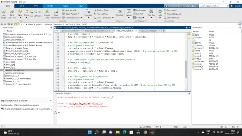
Solution 1: The variable pressure_2 spelling is wrong after that i changed the spelling.
Error 2:
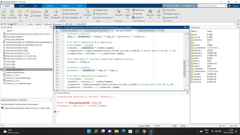
Solution 2: Same spelling mistake in variable pressure_3. After the error shows i changed it.
Error 3:
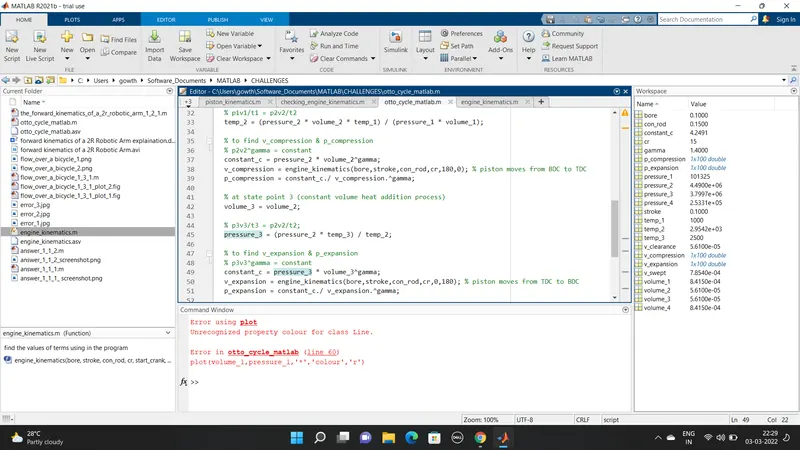
Solution 3: Matlab recognize the colour spelling as 'color'. But I have done the mistake in the spelling,after that I chnaged it.
Error 4:
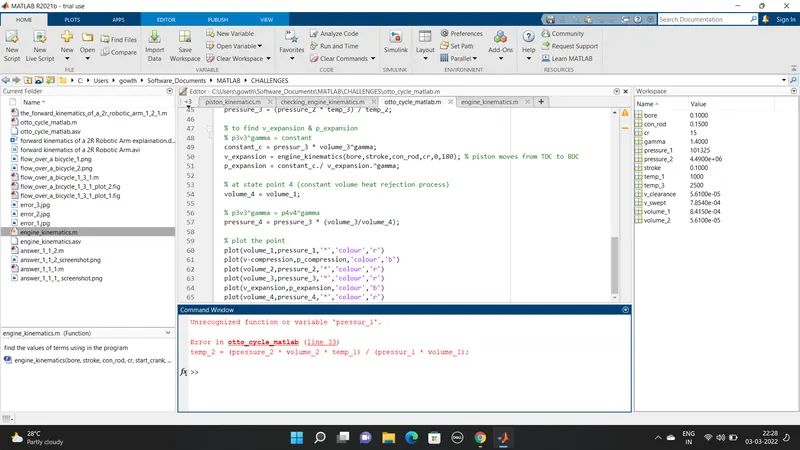
Solution 4 : The variable pressure_1 spelling is wrong. I changed it.
Error 5:
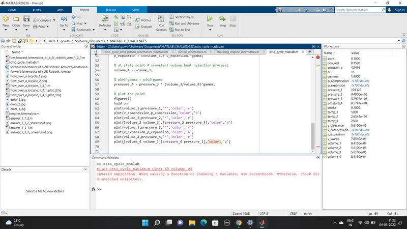
Solution 5: in plot command between the x and y values comma (,) should be use to differentiate the x and y values. but I forget to put it. After the error shows I changed it.