Week - 4
#Question : 1
Implement control logic of a “washing machine” using Stateflow as per given sequence:
- If the power supply is available, the system gets activated
- If the Water supply is not available, stop the process & indicate through LED
- Soaking time should be 200s followed by Washing time of 100s.
- Then rinsing happens for next 20s & dryer runs for 50s
After all the processes have completed turn on the finished LED
#Answer :
Aim : Implement control logic of a “washing machine” using Stateflow as per given sequence
Objective : In simulink, implement the control logic of a washing machine using state flow as per given input conditions, create a model and operate the model logic system and display the output of the results by using lamp indicator.
Explaination :
State Flow :
Stateflow provides a graphical language that includes state transition dia,flow charts, state transition tables, and truth tables. By using stateflow to describe how matlab algorithms and simulink models react to inputs signals,events,and time based conditions.
Control Logic :
Control logic is model system logic using state machines , flowcharts and truth tables.
Parameters :
Input data = Water Supply, Powern supply
Output data = water, soaking, rinsing,dryer, washing etc
Explaination for control logic of a washing machine using State Flow :
State flow is a simuilnk tool for implement the state machine. Here model system logic of a washing machine using state flow has been done.
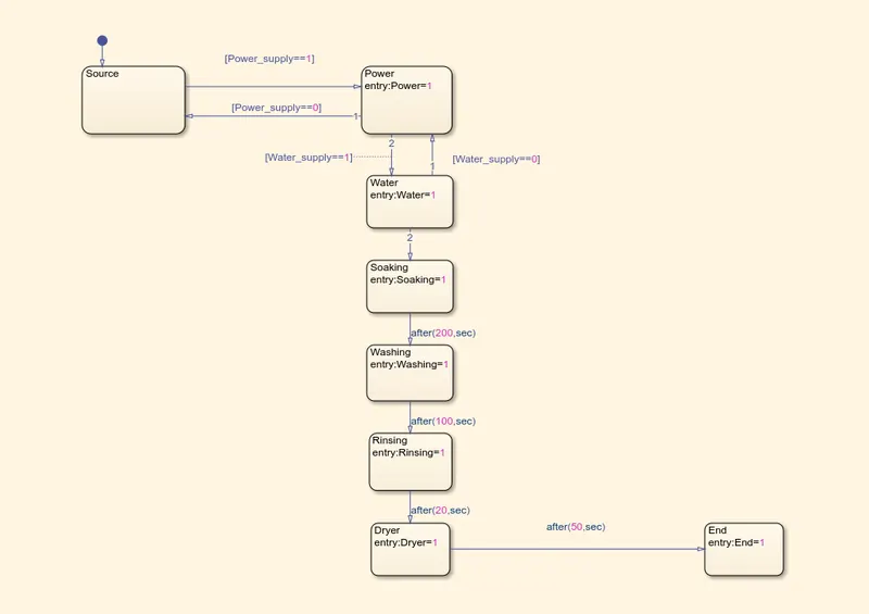
Step 1: Create a chart and enter the given input conditions
- If the power supply is available, the system gets activated
- If the Water supply is not available, stop the process & indicate through LED
- Soaking time should be 200s followed by Washing time of 100s.
- Then rinsing happens for next 20s & dryer runs for 50s
Chart are as given below :
Step 2 : After entering the input conditions in the chart, go to the symbol panel and assign the variables like input data and output data
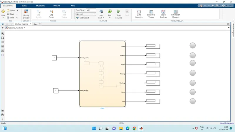
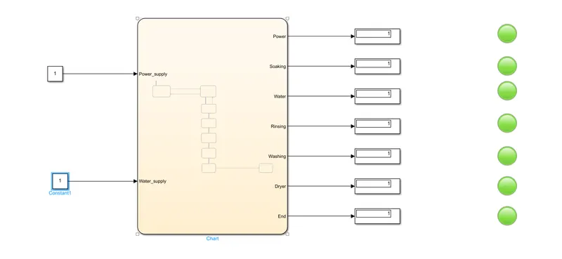
Step 3 : Give the input values for turning on or off the power supply and water supply, for this the constant block is used.
Note: For Both Supplies when we put the constant value 1 then the supplies are ON also when we put the value is 0 then the supply is OFF we can use alternate also because two constant blocks are used
Step 4 : Use Display block and Lamp indicator to display the results.
Washing Machine Model :
Output Results :
Control Logic of a washing machine using state flow has been implemented.
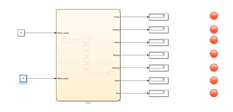
Case 1:
If the power is 0 i.e OFF then the system is not being activated.
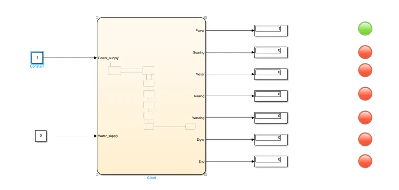
Case 2:
If the power is 1 i.e ON but the water supply is 0 i.e OFF then the because of water supply is off the system is diactivated which is off in working.
Case 3:
If the power is 1 i.e ON and water is 1 i.e ON then the system getting activated and all the lamps are getting green and the all processes are done and the machine is working in process.
Conclusion :
We can conclude that we simulate the washing machine control logic with the help of stateflow and get satisfactory result.
#Question : 2
Make a Simulink chart for the “Gear shift” logic as per below conditions:
Speed Range(kmph) Gear
0 to 15 1
16 to 25 2
26 to 40 3
41 to 60 4
Above 61 5
Give speed input while the simulation is running & display the gear number.
#Answer :
Aim : Make a Simulink chart for the “Gear shift” logic as per below conditions
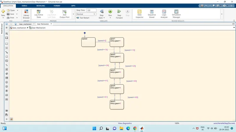
Objective : Simulink chart for the Gear shift logic as per below conditions --
Speed Range(kmph) Gear
0 to 15 1
16 to 25 2
26 to 40 3
41 to 60 4
Above 61 5
speed input while the simulation is running and display the gear shift which is output.
Parameters :
Input data = speed
Output data = gear
Control logic Model :
Explaination :
Step 1 : After entering the input conditions are given in question, go to symbols pane and assign the given variable, i.e input data, output data etc
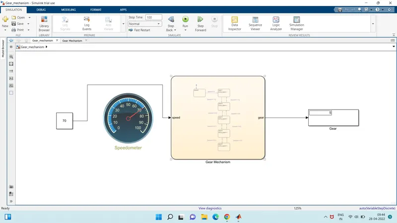
Step 2 : Create constant to give the exact speed to the gauge
Step 3 : Connect the speedometer gauge to vary the speed while simulation is running
Step 4 : Use display block to display the no of gear
Gear Shifting Model :
Output Results :
Case 1: When the given constant value is 10 then the speed reches the 10km/hr then we run the model the result is shown in the display block which is gear no i.e 1.
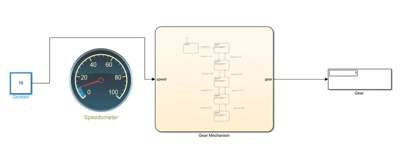
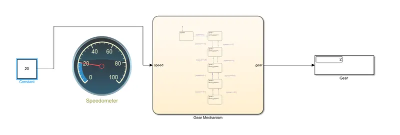
Case 2: When the given constant value is 20 then the speed reches the 20km/hr then we run the model the result is shown in the display block which is gear no i.e 2.
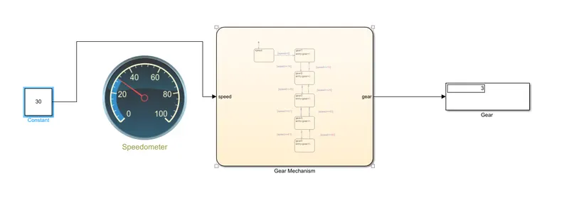
Case 3: When the given constant value is 30 then the speed reches the 30km/hr then we run the model the result is shown in the display block which is gear no i.e 3.
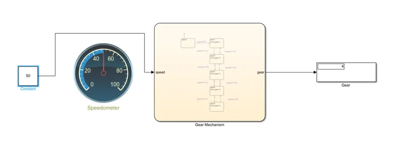
Case 4: When the given constant value is 50 then the speed reches the 50km/hr then we run the model the result is shown in the display block which is gear no i.e 4.
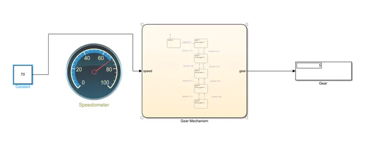
Case 5: When the given constant value is 70 then the speed reches the 70km/hr then we run the model the result is shown in the display block which is gear no i.e 5.
Conclusion :
We can conclude that we simulate the gear shifting control logic with the help of stateflow and get satisfactory result.