Week - 4
Q1.)Implement control logic of a “washing machine” using Stateflow as per given sequence:
THEORY :
STATEFLOW : - Stateflow provide the graphical language that includes state transition diagram ,flow chart,state transition table & truth tables. it is used to decribe how MATLAB algorithms and Simulink model react to input signals, events and tame based condition.State flow allows you to design and develop supervisory control, task, scheduling, fault management, communication protocols, user interface & hybrid system. With Stateflow, you model combinatorial & seuential decision logic that can be simulated as a block within a Simulink model or executed as an object in MATLAB. Graphical animation enable you to analyse and Debug your logic while executing. Edit time and run time check & ensure design consistency and completeness before implemenation.
CONTROL LOGIC :- Control logic is the key part of a Software program that control the operation of program. The control logic repond to the commands from the user & it also acts on its own to perform automated Task that have been structured in program. Controlled logic can be modelled using a state diagram, which is a form of hierarchical state machine.
OBJECTIVE : -
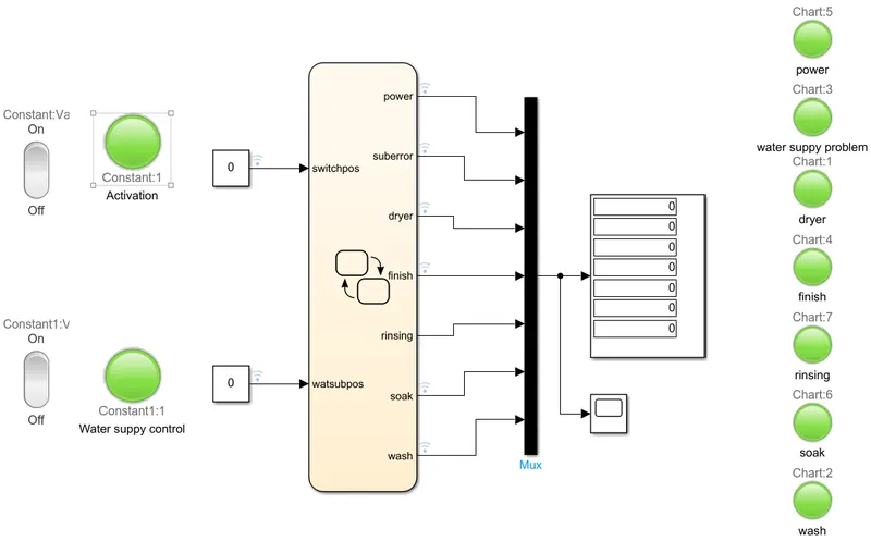
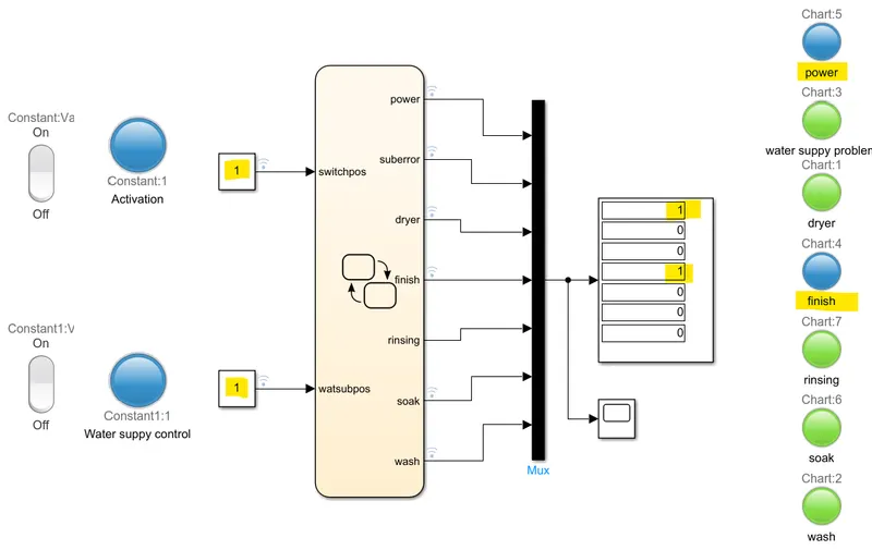
- The washing machine model is compromised of several LEDS,and two rocker switches and the state flow chart ,and a display and a MUX block.
Steps:
- The input signals are inputted through the swiches,then it is picked up by the connected leds.The leds are green when there is no signal and blue when a signal passes through them.
- Then it goes into the state flow chart,then all the outputs go through the other end and they trigger the Leds connected with them and then go through the mux which ccombines all the output signals into a single signal which can be easily connected to the display which displays an array of output data.The display shows 0 when when there is no signal in the respective output port and 1 when there is a signal in the respesctive output port.
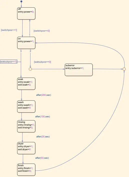 Chart was required to run the progam using as per provided parameters.
- initially the system is off
- when power is on ,it activates the corresponding led and it is transferred from the off state to the on state.
- Then it checks if water supply is available, if it is available, it starts the soaking process, if not it will output "suberror" and trigger the water supply led and then it is returned to the on state through the junction.
- upto this moment the system is event triggered from now on it is time triggered
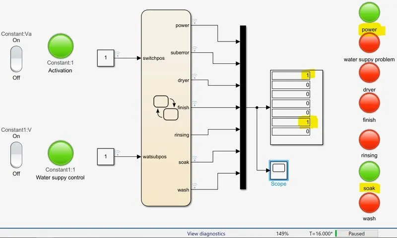
- then it will start the soaking process and trigger the corresponding led, then after 200 second it ends the state and as it exits it will stop this process which will deactivate the corresponding led
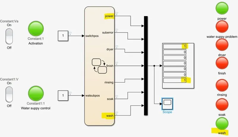
- then it will start washing for 100 seconds, and as it exits it will stop the process.
- then it will start rinsing for 20 seconds, and as it exits it will stop the process
- then it will start Drynig for 50 seconds, and as it exits it will stop the process.
- then it will turn the finnish Led.
- then it is returned to the on state through the junction.
In order to verify that the system is working correctly and performing all the functions,we make it run in steps:
RESULTS : All system OFF CONDITION NEUTRAL.
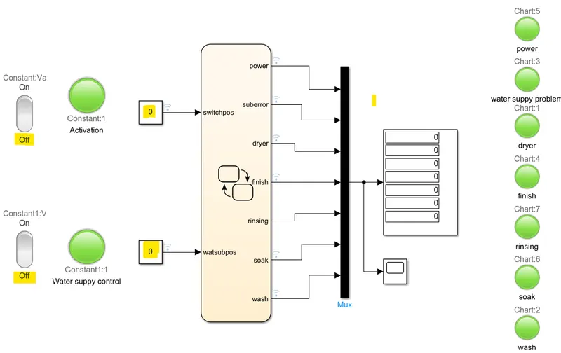 OFF
OFF 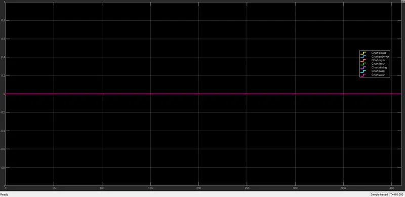 .
.
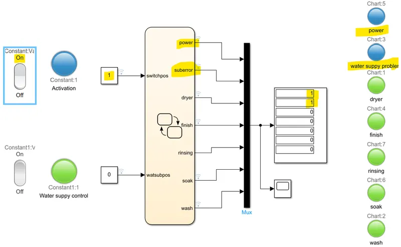
CONDITION 1 : POWER ON BUT WATER SUPPLY OFF CONDITION
- If the Water supply is not available, stop the process & indicate through LED
 POWER ON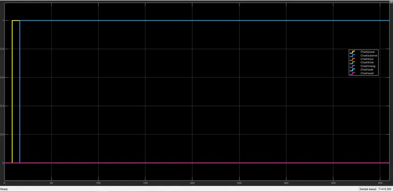
System gives water supply problem error
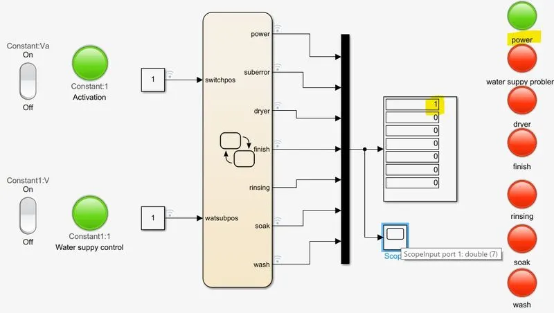
STATE 1: POWER ON
- If the power supply is available, the system gets activated.
 ON
ON 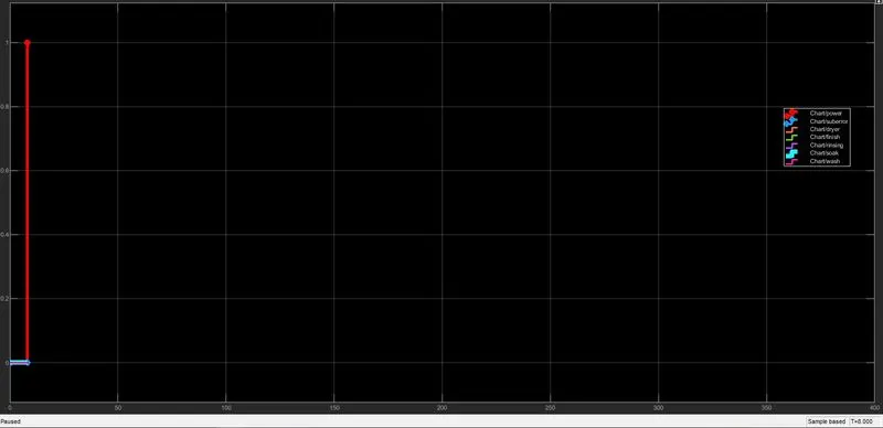 .
.
CONDITION 3 :
- Soaking time should be 200s followed by Washing time of 100s.
- soaking process after verifying there is a water supply, this step will take 200sec
 SOAK
SOAK 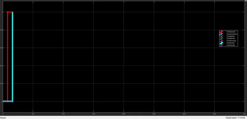 .
.
WASHING PROCESS
- this step will take 100 sec
 wash
wash 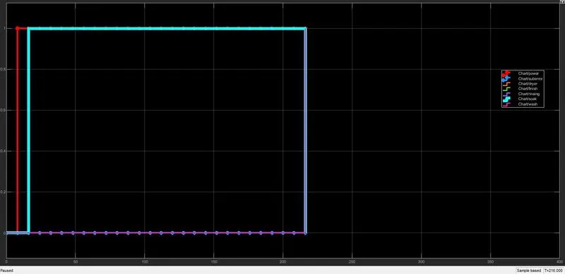 .
.
CONDITION :
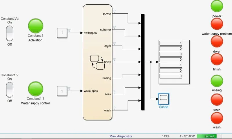
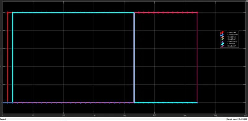
- Then rinsing happens for next 20s & dryer runs for 50s
RINSING PROCESS
- this step will take 20 sec
 RINSING
  .
.
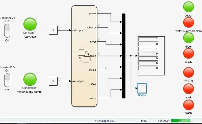
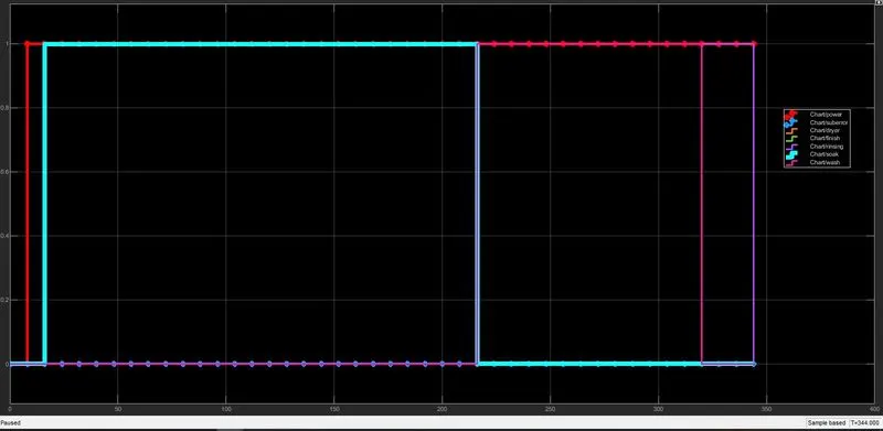
DRYING PROCESS
- this step will take 50 sec
 DRYING
  .
.
FINAL RESULTS : POWER ON / WATER SUPPLY ON it is final result shown on screen.
 FULL ON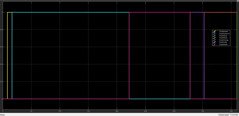
system works normally and give correct finsh.
>>>>>>>>>>>>OOOO<<<<<<<<<<<<<
Q2.) Make a Simulink chart for the “Gear shift” logic as per below conditions:
Speed Range(kmph) Gear
0 to 15 1
16 to 25 2
26 to 40 3
41 to 60 4
Above 61 5
Give speed input while the simulation is running & display the gear number.
THEORY :
A Manual transmission (also known as a manual gear box; abbreviated as Mt ) is a multi-speed transmission where gear change require the drive to select the gear by manually operating a gear stick and clutch (which is usually a foot pedal for car, or a hand lever for motorcycles).
Early automobile used sliding mesh manual transmission with up to three forward gear ratios. Since the 1950s, constant mesh manual transmission have become increasingly common place and the number of forward ration has increased to 5- speed and 6-speed manual transmission for current vehicles.
PROCEDURE :
- Create a Chart box for defining the stateflow as per the given condition.
- If the speed is less than 0 or equals to 0, the flow is Terminated and Gear 0 is Activated.at the Junction else 1 is carry forwarded.
- If the speed is Greater than 0 and less than or equal to 15, the flow is in activated and Gear 1 is Activated.
- If the speed is Greater than 15 and less than or equal to 25, the flow is in activated and Gear 2 is Activated.
- If the speed is Greater than 25 and less than or equal to 40, the flow is in activated and Gear 3 is Activated.
- If the speed is Greater than 40 and less than or equal to 60, the flow is in activated and Gear 5 is Activated.
- If the speed is Greater than 15, the flow is terminated and Gear5 is activated.
BLOCK DIAGRAM
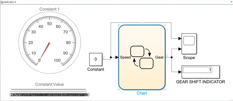
CHART DIAGRAM - (Control Logic Structure)
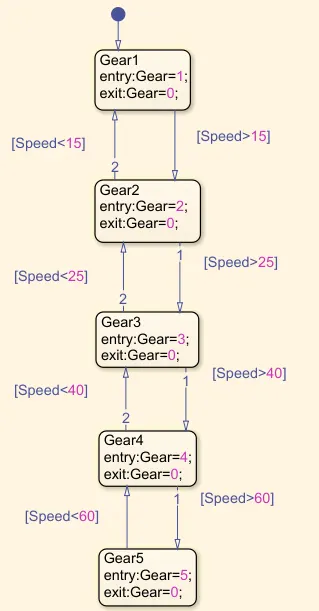 PARAMETERS
EXPLANATION :
- Here we have used "CHART BOX" to define the gear shift logic for the condition given above as per in objective.
- 1st we have define 5 states namely "GEAR_1" "GEAR_2" "GEAR_3" "GEAR_4" "GEAR_5".
- Now to shift from one state to another we have defined the conditions of the speeds as mentioned above.
- We have also defined the value inside the state which represent that when the particular state is going ON it will display the value that is defined in it. This will help us to see that which gear is operating at particular speed.
- The transition condition for gear shifty is decided as Given below :
Here we give SPEED as an INPUT for the chart.
Forward direction:
- Speed > 15 Shift to Gear = 2
- Speed > 25 Shift to Gear = 3
- Speed > 40 Shift to Gear = 4
- Speed > 60 Shift to Gear = 5
Reverse Condition :
- Speed < 60 Shift to Gear = 4
- Speed < 40 Shift to Gear = 3
- Speed < 25 Shift to Gear = 2
- Speed < 15 Shift to Gear = 1
Here we give GEAR as an OUTPUT for the chart. 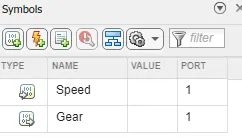
- After Flow chart is generated using some blocks from the library and there connection are done as mention below.
- A constant Block(Gear Transmission) is connected with slider gain block to provide initial input.
- Slider gain Block is use to define the speed by sliding the guage as per desire to change the speed during simulation is running and it acts as input for speed.
- The output port (Gear) is connected with the display wich is Renamed as GEAR SHIFT INDICATION helps to indicate the current engaged Gear for current speed in the slider gain.
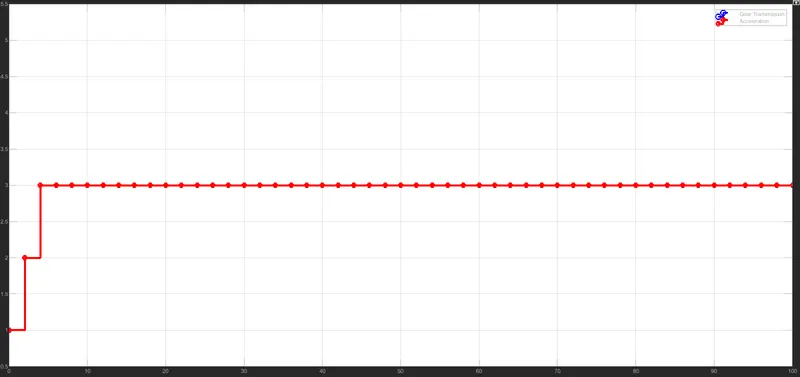
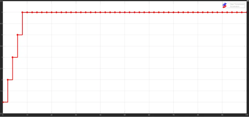
- The output port (Gear) is alos connected with scope which was helps to show the graph of GEAR TRANSIMISSION and ACCELERATION.
AT 1GEAR SPEED 15 PRESS RUN
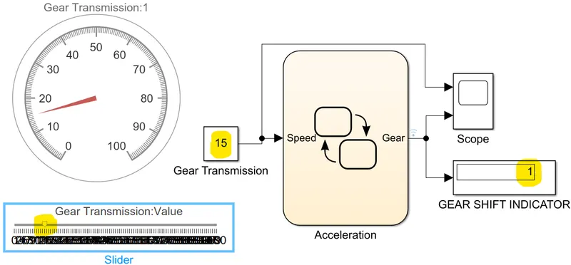 1ST GEAR
 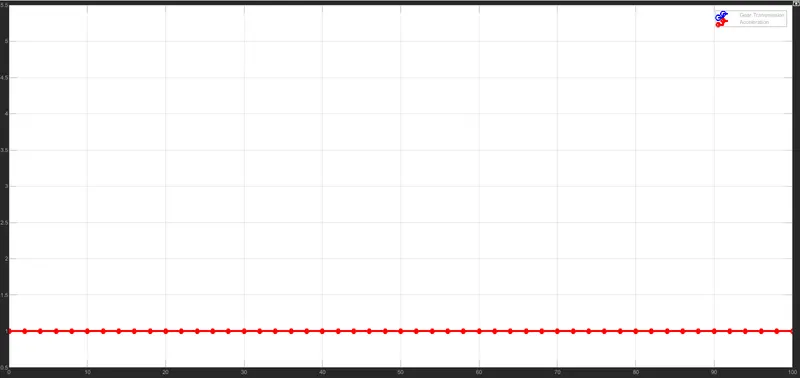 .
.
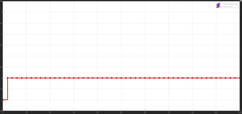
AT GEAR 2 SPEED 25
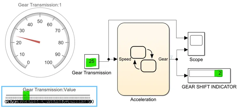 2ND GEAR
  .
.
AT GEAR 3 SPEED 40
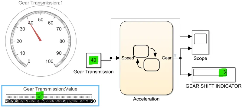 3RD GEAR
  .
.
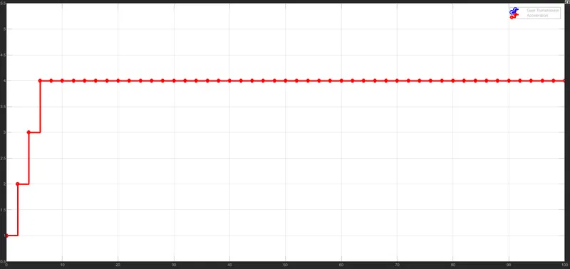
AT GEAR 4 SPEED 56
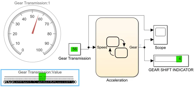 4TH GEAR
  .
.
AT GEAR 5 SPEED ABOVE 60
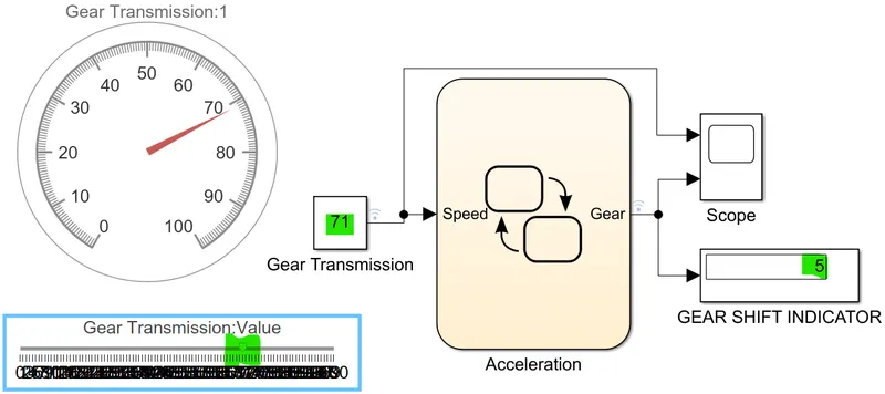 5TH GEAR
  .
.
CONCLUSION :
- All objective achive and run successfully.
- Similar concepts and approach can be adopt to create state flow for other systems.