Week - 4
AIM:
1. To implement control logic of a washing machine as per given sequence.
2. To make a Simulink chart for the Gear Shift logic as per given conditions.
MODEL LINK:
https://drive.google.com/file/d/1iso7dth_i_aNzmZzEIb6O-ejRTm0Buab/view?usp=sharing
MODEL IMAGE:
EXPLANATION:
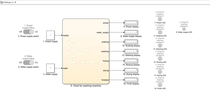
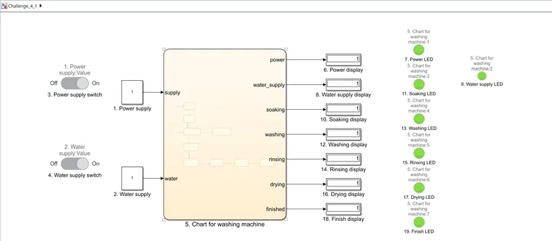
1. Power supply is represented by a constant block since its variation is 0 and 1.
2. Water supply is shown by another constant block and has values of 0 and 1.
3. Power supply is varied with the help of slider switch block.
4. Water supply is also varied by another slider switch block.
5. This block represents the chart of washing machine and its processes. It takes two inputs, power supply and water supply and gives 7 different outputs.
6. Display block for power. It is connected with power output of the chart and lamp block named as Power LED.
7. Lamp block which is connected to Power Display block.
8. Display block for water supply. It is connected with water supply output of the chart and lamp block named as Water supply LED.
9. Lamp block which is connected to Water supply Display block.
10. Display block for soaking process. It is connected with soaking output of the chart and lamp block named as Soaking LED.
11. Lamp block which is connected to Power Display block.
12. Display block for washing process. It is connected with wasing output of the chart and lamp block named as Washing LED.
13. Lamp block which is connected to Washing Display block.
14. Display block for rinsing process. It is connected with rinsing output of the chart and lamp block named as Rinsing LED.
15. Lamp block which is connected to Rinsing Display block.
16. Display block for dring process. It is connected with drying output of the chart and lamp block named as Drying LED.
17. Lamp block which is connected to Drying Display block.
18. Display block for completion of process. It is connected with finished output of the chart and lamp block named as Finish LED.
19. Lamp block which is connected to Finish Display block.
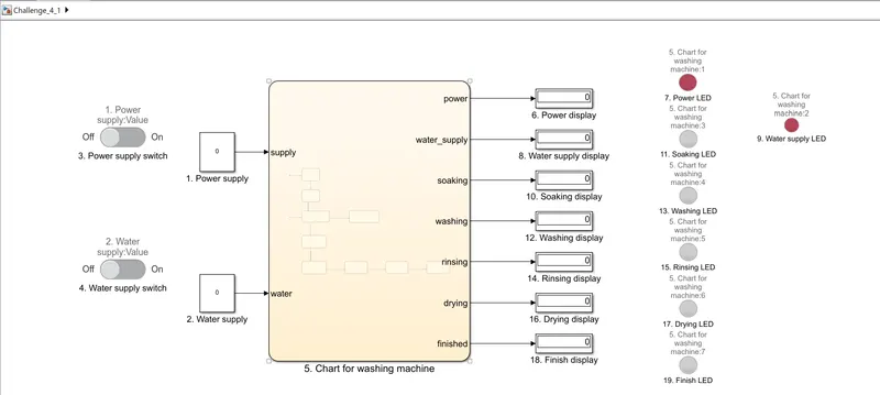
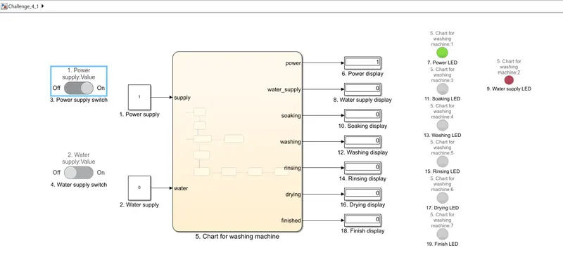
OUTPUT:
MODEL LINK:
https://drive.google.com/file/d/1cNeIcb_bR-f_yGAaU7dgpcpmqhZXgkxE/view?usp=sharing
MODEL IMAGE:
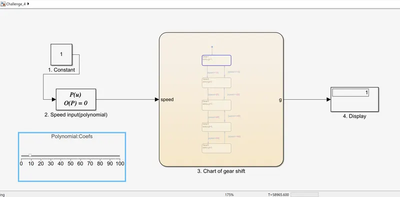
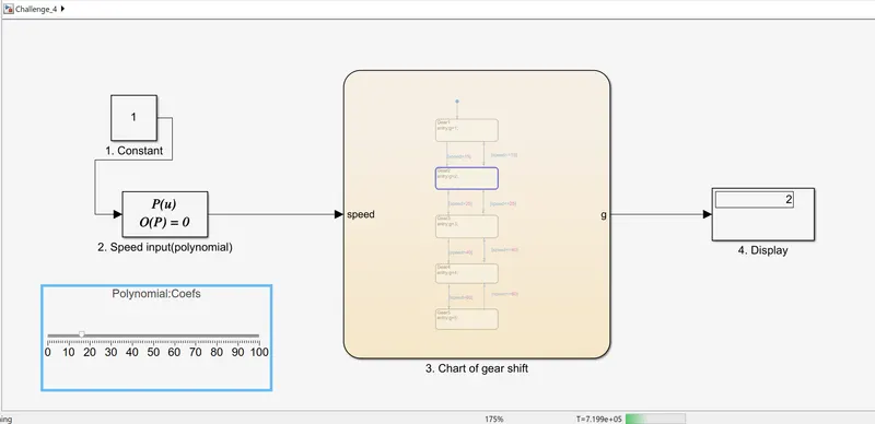
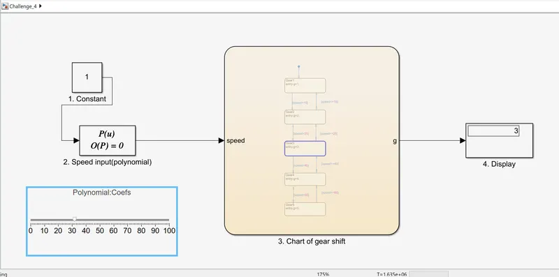
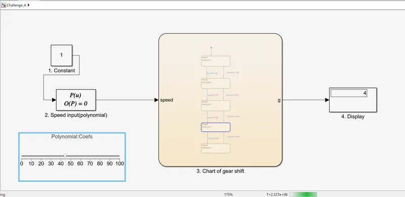
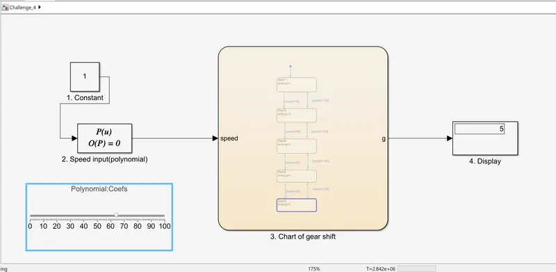
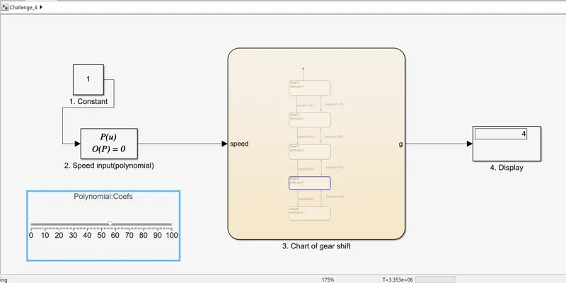
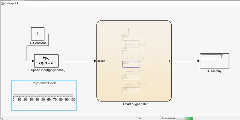
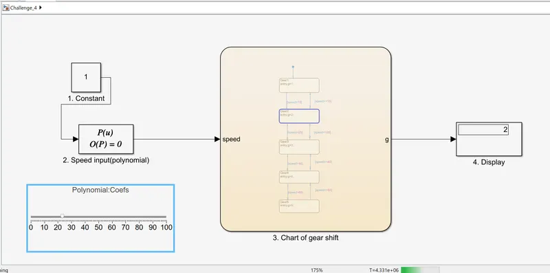
EXPLANATION:
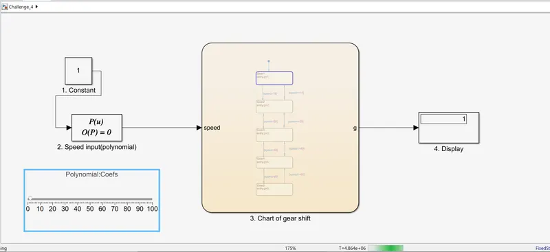
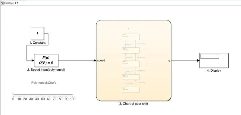
1. Constant block used as input for the polynomial block. It is used as input so that the speed signal is not time dependent and is manually controllable.
2. A polynomial block used for the speed input. It is connected to the slider block so as to change the value of coefficient and hence the value of input speed.
3. Block representing gear shift chart. It takes speed as the input and gives output as the gear number according to speed.
4. Display block for showing the gear number.
5. Slider block used to control the speed input. It is connected to coefficients column of the polynomial block.
OUTPUT: