Week - 4
1) Implement the control logic of a “washing machine” using Stateflow as per the given sequence:
- If the power supply is available, the system gets activated
- If the Water supply is not available, stop the process & indicate through LED
- Soaking time should be 200s followed by Washing time of 100s.
- Then rinsing happens for the next 20s & dryer runs for 50s
After all the processes have been completed turn on the finished LED
Blocks Used:-
Constant- 0&1 value represents Power and water supply on or off
Display-Indicates position of washing machine operations
Lamp- green shows operation ongoing and red shows operation end
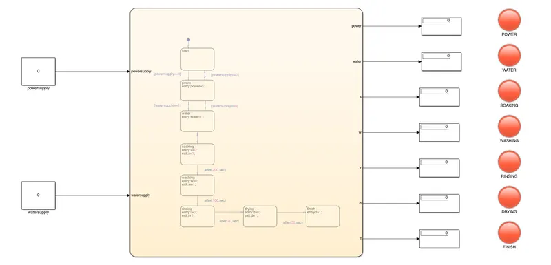
Stateflow Chart:-
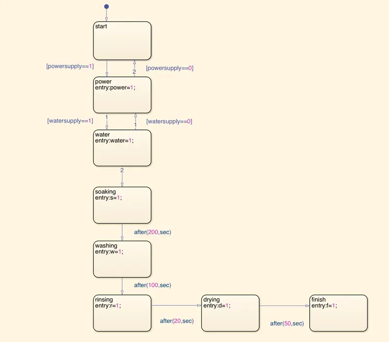
Explanation:-
Created chart which are having the following input conditions:-
- If the power supply is available the system will get activated.
- If the water supply is available the system starts or else stops the process.
- After that, soaking time should be followed for 200s, washing time of 100s then rinsing happens for the 20s and drying runs for 50s.
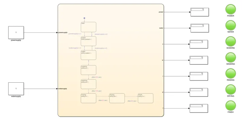
- After completing all the processes, turn on the finish LED.
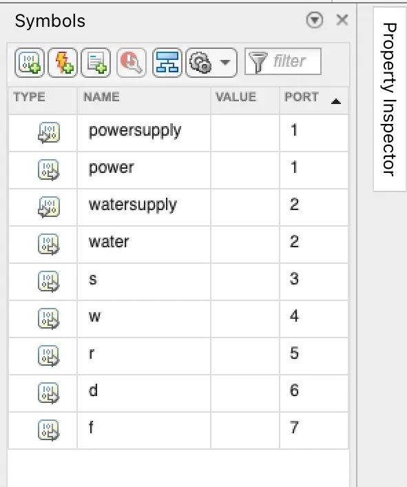
- Then Open the symbol pane and assign given variables like input data and output data.
- In the Constant block, if the value is 0 then the supply will turn OFF and if the value is 1 then the supply will turn ON.
- Display and Lamps will indicate the results
Symbol Pane:-
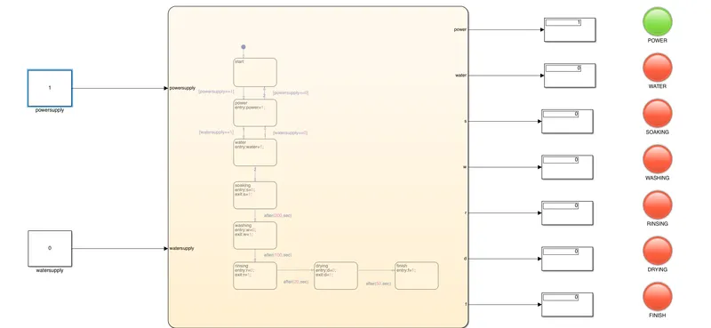
Power Supply ON position:-
Water Supply ON position:-
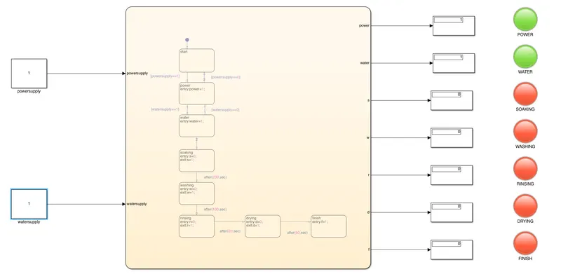
All processes are finished:-
Conclusion:-
We have created Stateflow logic for the washing machine model in a sequence which is mentioned in the question and after finishing all processes LED lights to turn green which indicated the process is finished.
2)Make a Simulink chart for the “Gear shift” logic as per below conditions:
Speed Range(kmph) Gear
0 to 15 1
16 to 25 2
26 to 40 3
41 to 60 4
Above 61 5
Blocks Used:-
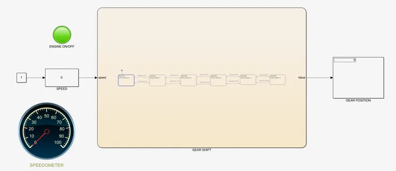
Lamp-To indicates engine on-off position.
Constant- 0 value to engine off and 1 value to the engine on
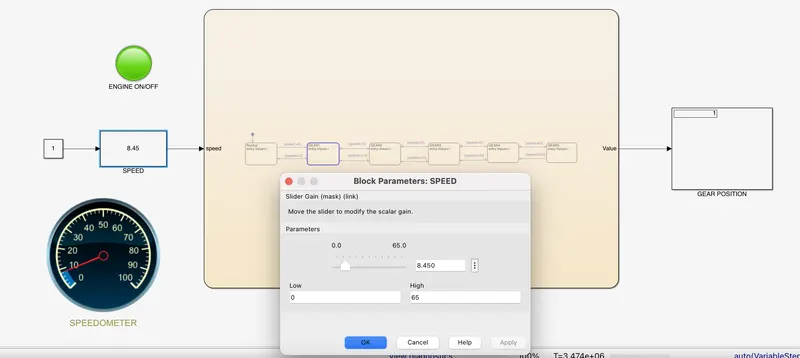
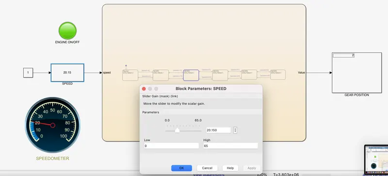
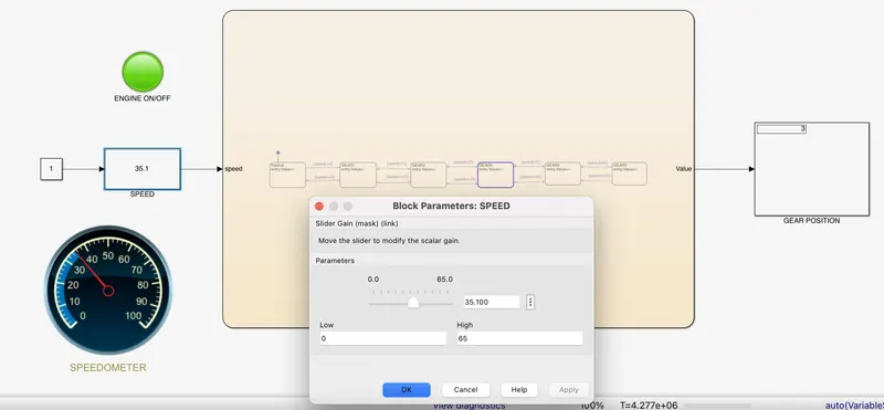
Slider gain- To increase engine speed gradually
Speedometer- To measure or show speed
Display- To show gear position
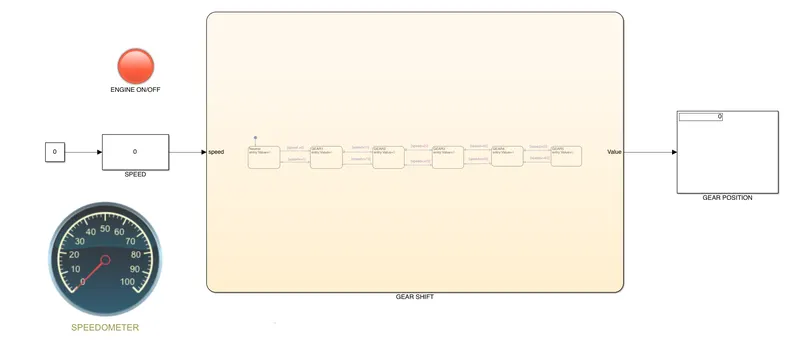
Explanation:-
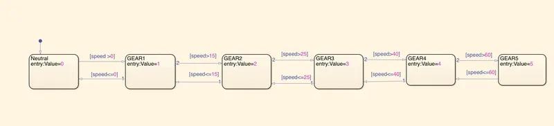
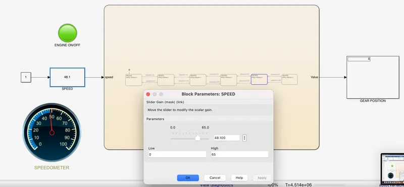
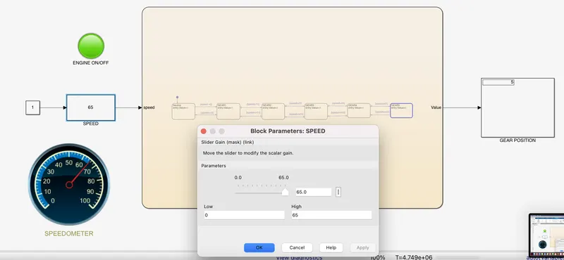
- We created Stateflow by using a chart where we created inputs and outputs conditions, after entering conditions in the chart go to the symbol pane and assign the given variables like input data and output data.
- By connecting the constant block to the lamp we can put values of 0 and 1 to represent the engine on and off.
- Connect the slider gain to vary speed while the simulation is running for infinite time.
- As per speed and gear position conditions which are mentioned in the chart, the display will indicate the gear position.
Stateflow chart:-
Engine ON Position:-
Gear 1 Position:-
Gear 2 Position:-
Gear 3 Position:-
Gear 4 Position:-
Gear 5 Position:-
Conclusion:-
We have created control logic for gear position as per the given conditions of speed and gear position for which we have used a Stateflow chart and a few Simulink blocks like slider gain, speedometer, display etc.