Week - 4
AIM
1)To Implement control logic of a “washing machine” using Stateflow as per given sequence:
- If the power supply is available, the system gets activated
- If the Water supply is not available, stop the process & indicate through LED
- Soaking time should be 200s followed by Washing time of 100s.
- Then rinsing happens for next 20s & dryer runs for 50s
After all the processes have completed turn on the finished LED
2). To Make a Simulink chart for the “Gear shift” logic as per below conditions:
Speed Range(kmph) Gear
0 to 15 1
16 to 25 2
26 to 40 3
41 to 60 4
Above 61 5
Give speed input while the simulation is running & display the gear number.
OBJECTIVE 1
INTRODUCTION
STATE-FLOW :- Stateflow is a control logic tool used to model reactive systems via state machines
and Flow charts within a simulink model. Stateflow uses a variant of the finite-state machine notation
established by David Harel, enabling the representation of hierarchy, parallelism and history within a
state chart.Stateflow also provides state transition tables and truth tables.
Stateflow is generally used to specify the discrete controller in the model of a hybrid system where the
continuous dynamics (i.e., the behavior of the plant and environment) are specified using Simulink.
Specific applications for Stateflow include:
- Mode logic, where each discrete mode of a system is represented by a state
- Fault management, where the Stateflow chart is used to control how the system responds to faults
and failures within a system.
- Task scheduling, where the Stateflow chart is used to schedule when specific tasks occur, either within
the Stateflow chart or within the overall Simulink model.
Most modern washing machines are fully automatic. A fully automatic washing machine completes the entire
clothes washing cycle without any effort from the user. It will rinse, wash, agitate, and spin dry clothes
all on its own.
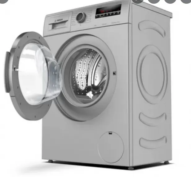
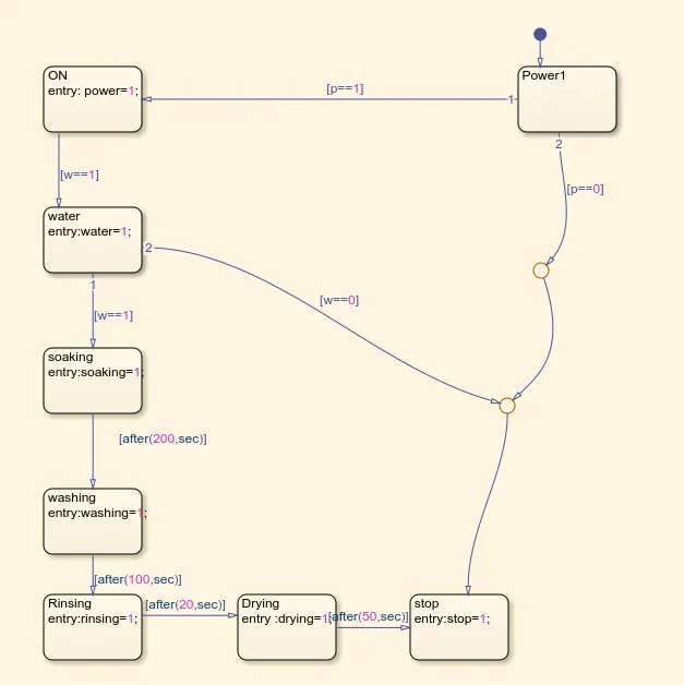
STEP 1 :- Use chart block to create the flow chart by given inputs conditions.when the power is available it -
transit to the next state ,is the water availabkle or not.if the water is available,the transition is true to move to
the next state which is SOAKING. If the water is not available the condition is false and the system will not
move towards next steps. If the condition is true the system state follows the states SOAKING,WASHING -
RINSING,DRYING and there by FINISHING by using of the respective time delay .
STATE FLOW CHART
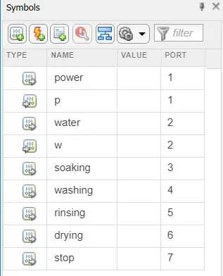
Use symbol pane option to define the input and outputs of the block.
MODEL :-IF BOTH POWER AND WATER AVAILABLE
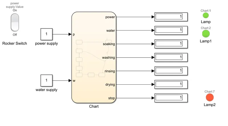
BLOCKS USED
Rocker Switch :- we assaign the values of switch ON=1 and OFF=0 ,then connect it to the constant block of power -
supply . if we turn ON the switch value of 1 is transmited to the constant block and the system will turns ON and if
we turn OFF the switch the value 0 is transmited to the system.
Lamp:- Here the lamps are used to show whether the power is transmitted by showing green light and whether the
water is available by showing the green light or else the red light is showned.we assaigned a red light to the chart 7
to indicate the whole process is done or STOP.
IF WATER IS NOT AVAILABLE
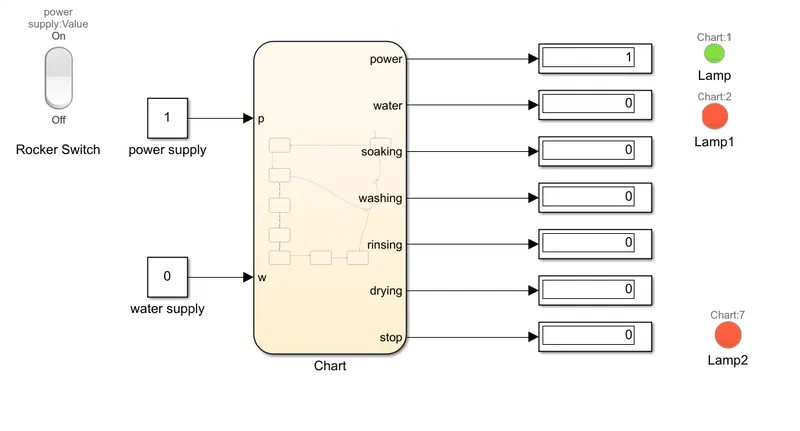
If water is not available the input of water supply remains 0 to the state so the lamp indicates a red colour based
on the system condition and state also stopped to transmitt to the next conditions.
OBJECTIVE 2
To Make a Simulink chart for the “Gear shift” logic as per below conditions:
Speed Range(kmph) Gear
0 to 15 1
16 to 25 2
26 to 40 3
41 to 60 4
Above 61 5
Give speed input while the simulation is running & display the gear number.
MODEL EXPLANATION
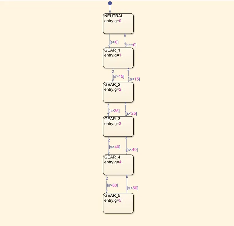
By using CHART BLOCK In SIMULINK create a flow chart by given input condition of speed and the output is gear,
when the speed is less than 0 the gear is in the idle condition and if the speed is >0 the state changed to gear1 and
for speed>15 the gear will changed to gear 2, and for speed>25 to the third gear,for speed>40 automaticaly the gear
will changed to gear 4 and for speed>60 the gear is fifth and wiseversa for down chart.
FLOW STATE
MODEL
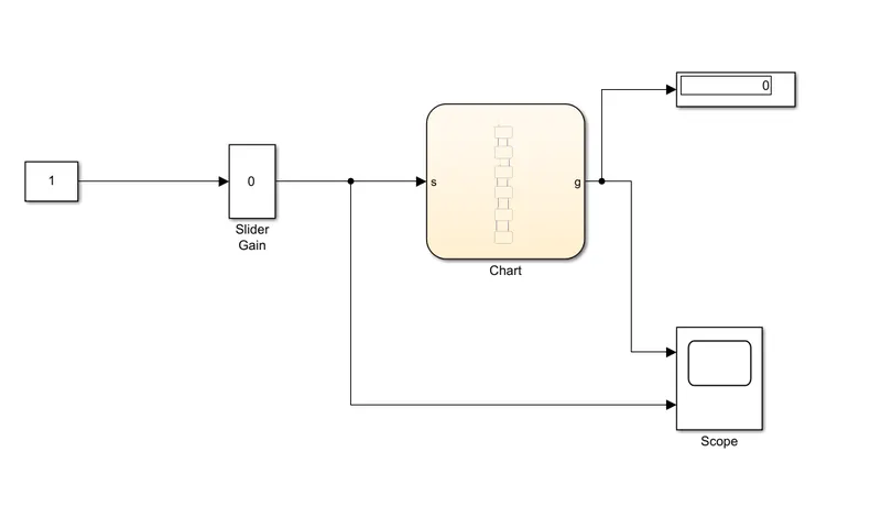
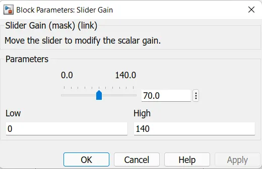
SLIDER GAIN BLOCK :- We can adjust the with the help of this block by setting lower limit as 0 speed and a high
speed of 140 as per the engine characteristics.
OTHER BLOCKS USED
- Constant block
- Slider gain block
- Chart block
- scope
- Display
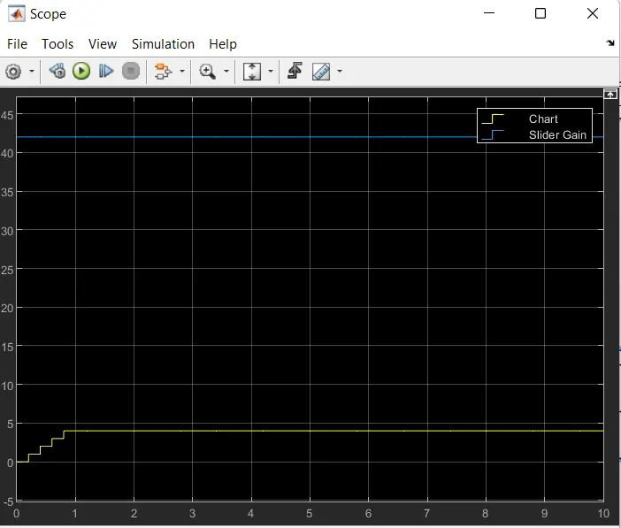
OUTPUT