Week -2
AIM
- To make a simulink model of doorbell using solenoid block with the given details and assumed parameters
- To use a thermister to sense the temparature of a heater and turn ON or turn OFF the fan as per the -
below conditions .
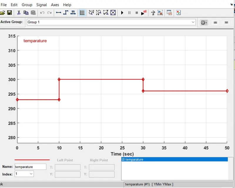
*Temparature source 20+273k from 0 to 10 sec
27+273k from 10 to 30 sec
23+273k from 30 to 50 sec
turn the fan ON , if the temparature above 25+273k ,otherwise OFF
DOORBELL
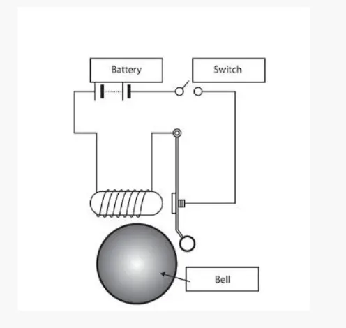
Doorbell is a electro-mechanical system ,which completes a electro-mechanical circute when turning ON the switch . While
turning the switch ON , the electric current passes through the circute and magnetise the electro magnet . The magnetic -
field generated by the electro-magnet is then used to power a mechanism that creates a doorbell action .
OBJECTIVES
- create a situation where the switch is closed for 2 sec and then released , observe the physical movement of the -
plunger .
SIMULINK MODEL
MODEL EXPLANATION
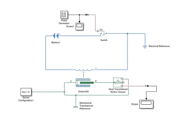
- A switch which controlled by the pulse generator to give the input conditions of time,amplitude ..etc ,that is -
for the total 4 sec of time the switch is turned ON for 2 seconds and OFF for another 2 seconds .
- Connecting a battery source series to the switch assembly for the input current .
- Connecting a solenoid block along with the battery and switch .
- Use a ideal Translational motion sensor to sense the movement of plungeron the solenoid block .
- A scope is connected along with the ideal translational motion sensor to analyse the graphical representation -
regarding the movement of the plunger .
- Using solver configuration and mechanical translational references to complete the model without an error .
BLOCKS USED IN THIS MODEL
1) Pulse generator :- pulse type determines the computational technique used .Time based is recommented for use with
a variable step solver,while sample based is recommented for use with a fixed step solver .
2) Switch :- if the external physical signal PS is greater than the value specified in the threshold parameter, then the -
switch is closed otherwise the switch is open .
3) Battery:- the battery block has four modeling variants ,accessible by right clicking the block in your block diagram -
and then selecting the appropriate option from the context menu,under simscape>Block choices .
4) Solenoid :- The plunger maximum stroke is implimented as a hard stop ,the dynamics of which are set by the contact
stiffness and contact damping parameters . the spring constant parameter is used to impliment a spring force that
pulls the plunger out .
5) solver configuration :- Each physical network represented by a connected simscape block diagram requires a solver
configuration for simulation . it specifies the solver parameters that your model needs before you begin simulation
6) Ideal translational sensor :- it measures displacement and velocity in a mechanical translational system .here we -
analyse the displacement of plunger w.r.t time .
7) scope :- scope is used to analyse the graphical representation of the output that is movement of the plunger and the
opening and closing of switch w.r.t time.
PULSE GENERATOR OUTPUT
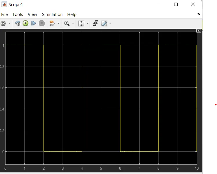
for each 2 second switch turns ON and OFF .
OUTPUT
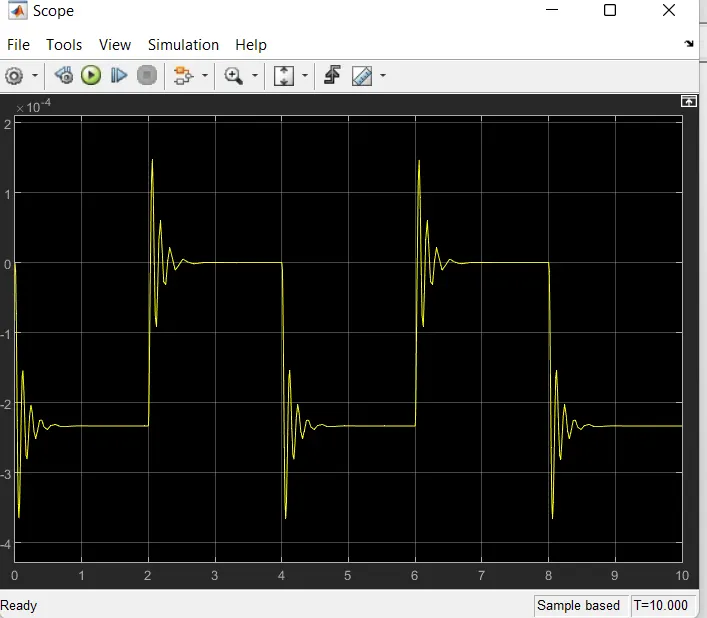
Visualisation of plunger movement with respect to time .
OBJECTIVE 2
Use a thermistor to sense the temparature of a heater and turn ON and OFF the fan as per the conditions .
INTRODUCTION
Thermistors are temperature-dependent resistors, changing resistance with changes in temperature. They
are very sensitive and react to very small changes in temperature. They are best used when a specific -
temperature needs to be maintained, and when monitoring temperatures within 50°C of ambient.
MODEL
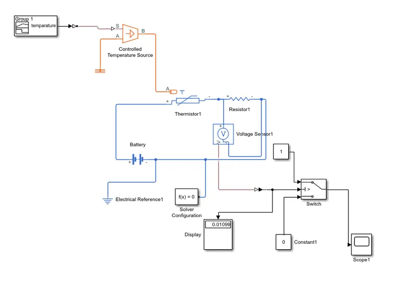
MODEL EXPLANATION
A Signal builder is used to build temparature in required conditions and connected to a controlled temperature source along
with the thermistor block .Resistor and battery source is connected series with the thermistor to complete the current flow
through the circute .A voltage sensor is provided parallely with the resistor to measure the voltage across the resistor .
the output of the voltage values are connected to the switch model which determines the switching ON and OFF of the
fan assembly w.r.t the threshold values .
NOTE* - In order to obtain the threshold value of the switch uncommenting the signal builder and we use a constant value
of 25+273=298 k as the input to the temperature source . By attaching a display along with the output of voltage sensor
we can obtain the threshold value that is 0.01189 here.
after this ,we can attach the signal builder and by giving this threshold value to the switch and the corresponding graph can
be analysed by using a scope .
BLOCKS USED
Signal builder :- This block is used to make own signals with respect to the prespectives. here tempatarure values w.r.t.time
is used to build the signals as the inputs.
Controlled temparature source :-This block represents an ideal energy source in a thermal network that can maintain a
controlled temperature difference regardless of the heat flow rate. The temperature difference is set by the physical signal
port S. A positive temperature difference causes the temperature at port B to be greater than the temperature at port A.
Thermistor :-This block represents an NTC thermistor using the B-parameter equation. The resistance at temperature T is
given by R(T) = R0*exp(B*(1/T-1/T0)) where R0 is the Nominal resistance at the reference temperature T0, and B is the
Characteristic temperature constant. The temperature T of the thermistor is governed by the equation m*c*dT/dt = Q where
Q is the net heat flow into port A, m is the mass and c is the lumped specific heat capacity
Resistance block :-The positive and negative terminals of the resistor are denoted by the + and - signs respectively. By
convention, the voltage across the resistor is given by V(+)-V(-), and the sign of the current is positive when flowing through
the device from the positive to the negative terminal. This convention ensures that the power absorbed by a resistor is always
positive.
Voltage sensor :-The block represents an ideal voltage sensor, that is, a device that converts voltage measured between any
electrical connections into a physical signal proportional to the voltage.
Switch :-Pass through input 1 when input 2 satisfies the selected criterion; otherwise, pass through input 3. The inputs are
numbered top to bottom (or left to right). The first and third input ports are data ports, and the second input port is the control
port. The criteria for control port 2 are u2 >= Threshold, u2 > Threshold or u2 ~= 0.
Scope :- Scope is used to visualise or analyse the graphical representation of inputs/outputs.
OUTPUT