Week - 4
1) Implemention of control logic of a “washing machine” using Stateflow as per given sequence.
Description:
Stateflow is used to implement the given control logic of a washing machine.
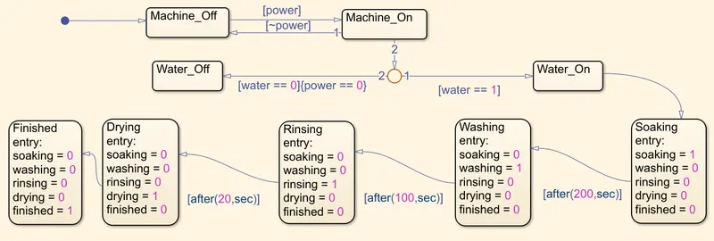
Conditions include Power on/off, water supply on/off, followed by 4 washing stages, soaking, washing, rinsing and drying, each continuing for certain given time period.
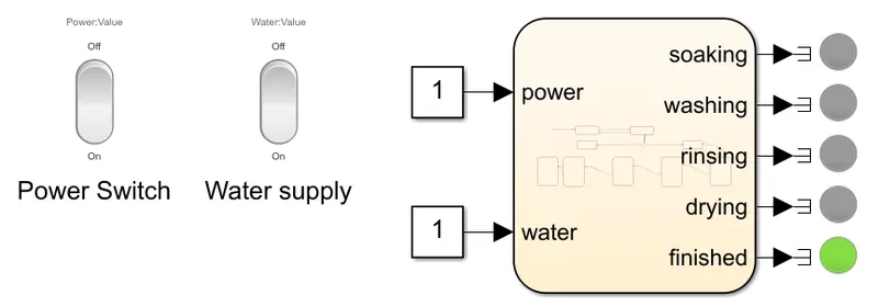
LED lights are added to indicate current stage and completion.
Step-wise explaination:
- Rocker switches are used to toggle power supply and water supply on/off.
- Inside stateflow chart, two state blocks are added for power on and power off modes.
These states transition to on another based on 'power' variable value. - Machine_On state is connected by a junction, which is the connected by another two states for water supply on & water supply off. Transition conditions are based on 'water' variable value. 'Water supply off' state transition is accompanied by the action- 'power off'.
- Now the washing stages are connected to 'water on' state. Each stage has a state block which contains on/off values for led lights. Each stage is followed by the next stage with time intervals in between. Time intervals are given using 'after' command in transition condition.
- On/off values of variables for each stage is taken out of stateflow chart as an output.
- 'Finished state block' is connected to the last washing stage. This too contain variable values for LED indicator.
- Coming out of the stateflow chart, each output is connected to 'terminator' block.
LED indicators are arranged beside each washing stage.
Output:
- Power on; water supply on: Reaches finished state.
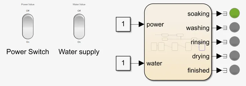
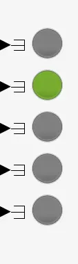

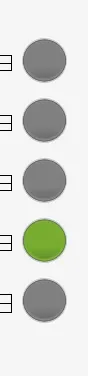
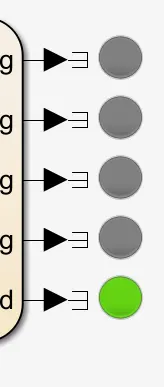
- Power on; water supply off: Machine turns off.
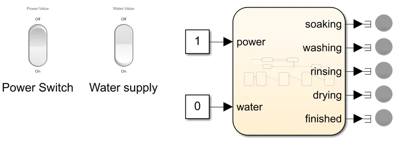
- Power off: Machine doesn't run.
2) Making a Simulink chart for the given “Gear shift” logic.
Description:
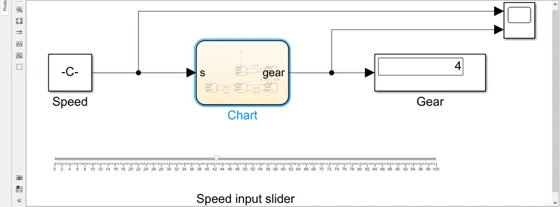
Gear shift logic according to the given speed-gear data is made using stateflow chart.
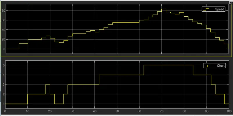
Speed input is user controlled during simulation. The chart then outputs the gear number according to the speed value. Speed is changed during simulation to get gear value and is seen through scope block and display block.
Step-wise explaination:
- 'Slider input' block is connected to the 'constant' block. Slider input range is selected from 0 to 100.
- This is given as input to stateflow chart named as variable 's'.
- Default transition arrow is connected to Gear1 state which is then connected to Gear2 state and so on.
Consecutive states are connected by transition arrows in both ways, stating the speed conditions given in the question. - Each state has 'gear' variable in entry state action, whose value is equal to respective gear. This is the output of the stateflow chart.
- Coming out of the chart, the output gear value is seen through display block.
Input speed & respective gear values are seen through scope block.
Output:
- Scope: Speed is controlled using slider. Gear shift is seen in second graph.