Week - 4_Implement control logic of a “washing machine” using State flow. & Make a Simulink chart for the “Gear shift” logic
Q1 .Implement control logic of a “washing machine” using Stateflow as per given sequence:
- If the power supply is available, the system gets activated
- If the Water supply is not available, stop the process & indicate through LED
- Soaking time should be 200s followed by Washing time of 100s.
- Then rinsing happens for next 20s & dryer runs for 50s
After all the processes have completed turn on the finished LED
ANS:
Objective: Implement control logic of washing machine using stateflow as per given sequence.
Theory:
Washing Machine: A washing machine is home appliance used to wash laundry.washing machine use to wash various type of clothes without apllying any physical effort.the washing machine is also called a cloth wash clothes automatically without having to supervise its operation.first you have to put the cloths in the machine and select the wash mode.than the machine automatically takes in the amount of water and washing powder as per required and machine automatically set the timing foe washing ,rinsing and drying as per the selected mode of wash .
Stages of washing The Cloth :
As per working of washing machine the working of machine is divided into mainly 4 stages.
These helps you to understanding better and pick the option depending on the basic of need.
1.pre wash (soaking)
2.washing
3.rinsing
4.spinning
Now we see these stages of washing machine for washing the clothes in simulink .
Modelling of washing machine in simulink :
This is basic simulink model of washing machine desgined for operating under given conditions:
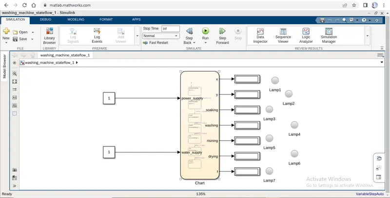
The below is the stateflow model designed or coded with that conditions which help the run model as per given condition in right time.
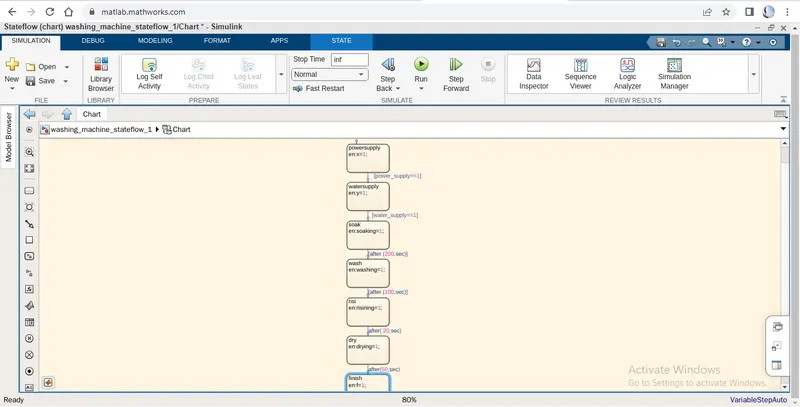
Obsevation:
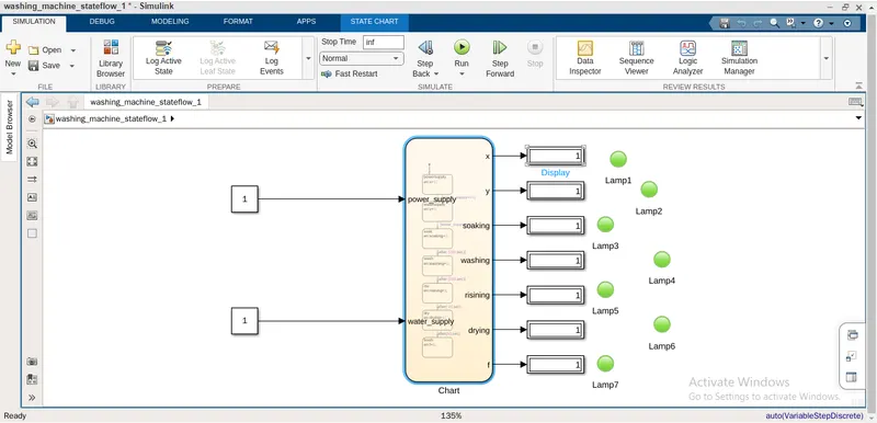
The following steps involves in the process we go to step by step:
1.Switched off when the system are in non operational condition(all lamps are off)
2.power supply is given to machine (Lamp glow)
3.as next step water supply given to the machine (Lamp 1 glows in green colour)
4.after the delay of 200 sec soaking action command given to machine.(Lamp 3 glow)
5.after soaking for 100 sec than next washing command given to machine(lamp 4 glow)
6.Rinsing command given to machine after washing,its starts rinsing the cloths for 20 sec(lamp 5 glow)
7.drying command takes place when rinsing process is done for 50 sec (lamp 6 glow)
8.finally end the process of all command of action and all lamps glow green.
Conclusion:
I try to define all given conditions and terms to execute in these model as given time and sequence condition.Hopefully these model run and it gives me all desired ouput that I want.
______________________________________________________________________________________
Q2. Make a Simulink chart for the “Gear shift” logic as per below conditions:
Speed Range(kmph) Gear
0 to 15 1
16 to 25 2
26 to 40 3
41 to 60 4
Above 61 5
Give speed input while the simulation is running & display the gear number.
Answer:
Objective : to create a sate flow chart for the gear shift in the simulink as per the below conditions given:
The given codition is coded in state flow chart which I have mentioned below:
Speed Range(kmph) Gear
0 to 15 1
16 to 25 2
26 to 40 3
41 to 60 4
Above 61 5
The following block sets are used for creating this model below simulink:
1.state flow chat
2.slider gain
3.constant
4.dispaly
These is the final stateflow model for gear shift logic system:
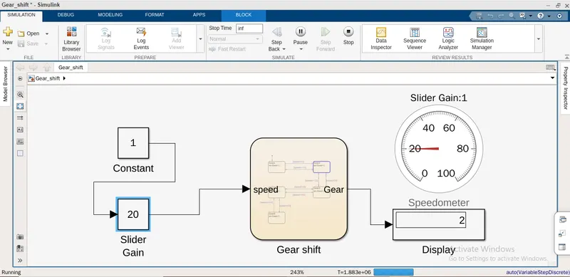
These is the stateflow chart model for gear shift logic system:
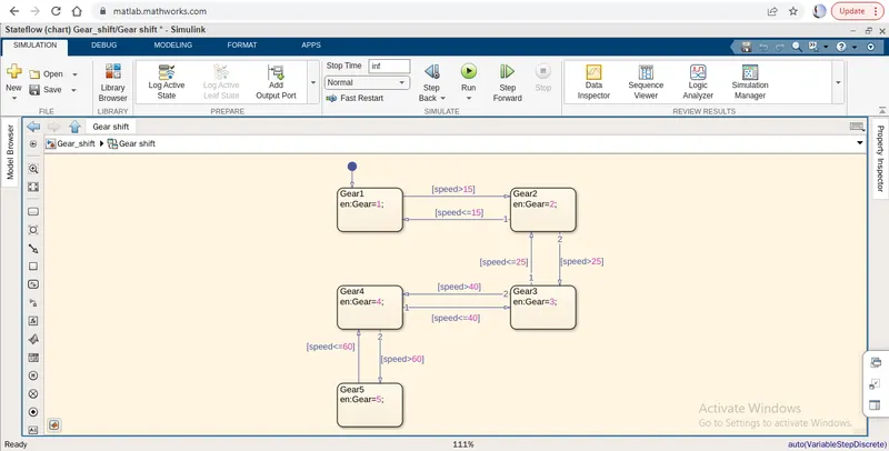
Above simulink model of gear system at different speed conditions.
1.when the speed is just 0 at start condition ,Gear should be in No 1.
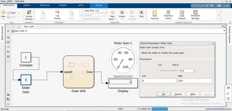
2.when speed range is upto 15km/h gear remains at gear 1 condition the gear will be unchanged.
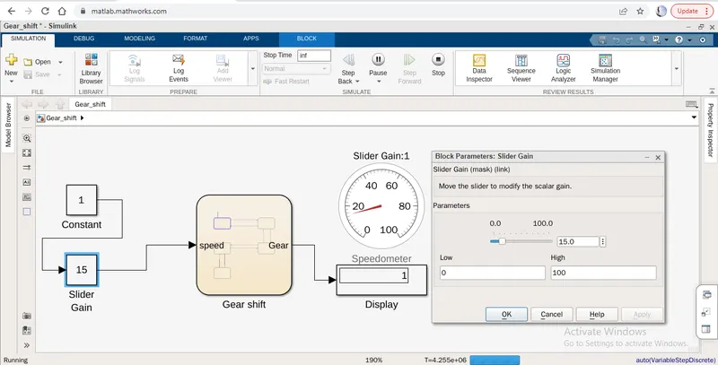
3.when speed range is upto 25km/h gear change the condition from 1 to in gear 2.
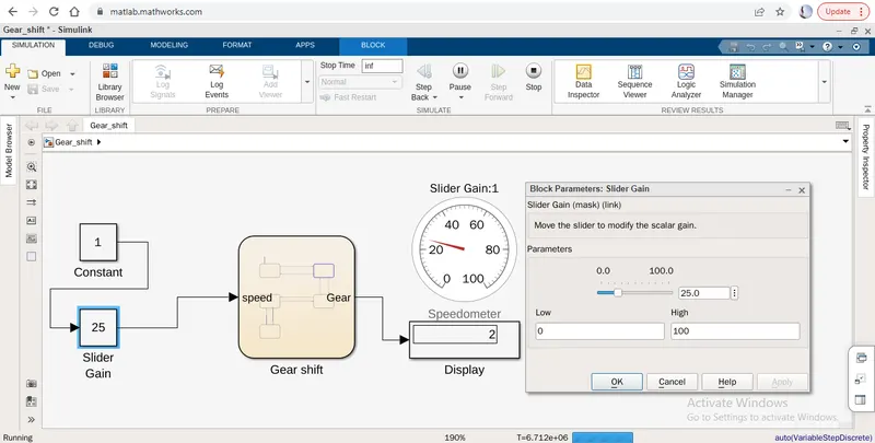
4.when speed range is upto 30 km/h gear change the condition from 2 to in gear 3.
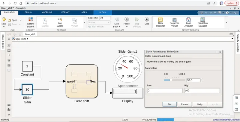
5.when speed range is upto 50 km/h gear change the condition from 3 to in gear 4.
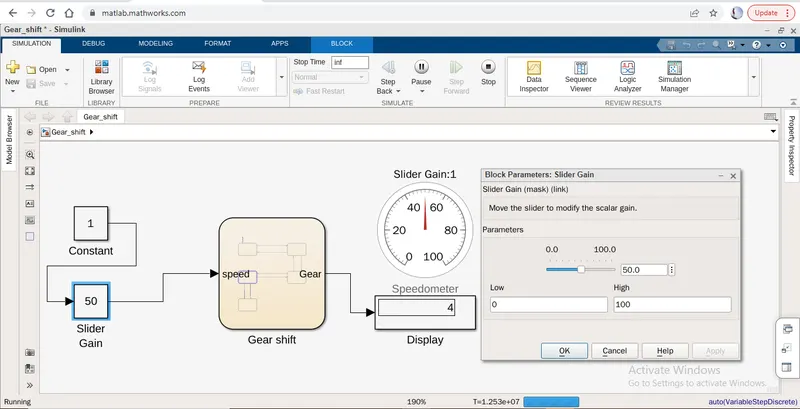
6.when speed range is upto 65 km/h and above that gear change the condition from 4 to in gear 5.
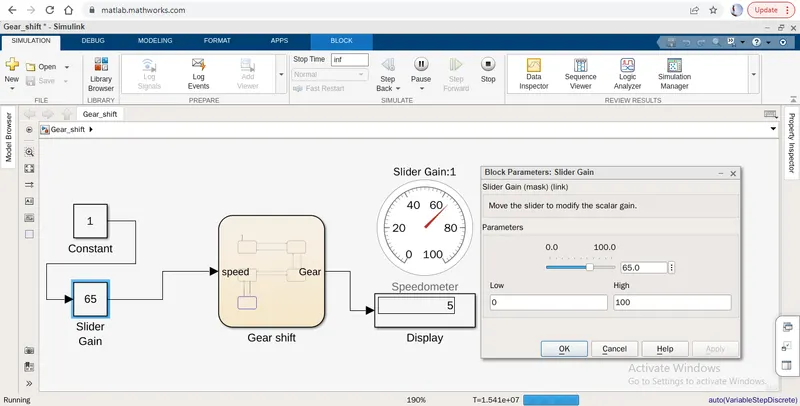
Here all output is as same as the given condition.
Conclusion:
I had create the simulink model and run for particular time period so i can understand the gear shifting logic in simulink. so I try to define all given conditions and terms to execute in these model as given speed and gear condition.Hopefully these model run and it gives me all desired ouput that I want.