Project-1: Powertrain for aircraft in runways
QUESTION:
Part A:
1. Search and list out the total weight of various types of aircrafts.
2. Is there any difference between ground speed and air speed?
3. Why is it not recommended to use aircraft engine power to move it on the ground at Airport?
4. How an aircraft is pushed to runway when its ready to take off?
5. Learn about take off power, tyre design, rolling resistance, tyre pressure, brake forces when landing.
Part B:
6. A. With necessary assumptions, calculate the force and power required to push / pull an aircraft by a towing vehicle.
B. Develop the model for the calculated force and power using Simulink.
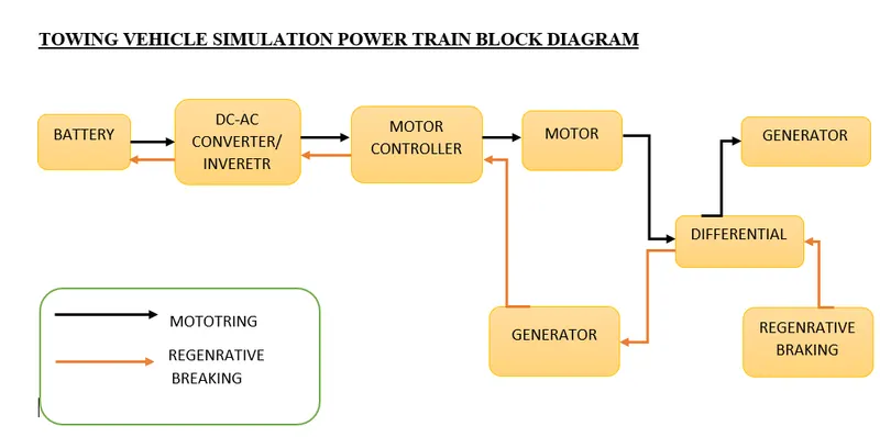
7. A. Design an electric powertrain with type of motor, it’s power rating, and energy requirement to fulfill aircraft towing application in Simulink. Estimate the duty cycle range to control the aircraft speed from zero to highest. Make all required assumptions. Prepare a table of assumed parameters. Draw a block diagram of powertrain.
(Hint :DC7 Block)
B. Also, Design the parameters in excel sheet.
ANS:
PART A:
ANS 1:
The List of total weight of various types of aircrafts is as follows .
These are total weights of various types of aircrafts are:
- AIRCRAFT GROSS WEIGHT
- MAXIMUM RAMP WEIGHT
- MAXIMUM LANDING WEIGHT
- REGULATED TAKE OFF WEIGHT
- MAXIMUM TAKE OFF WEIGHT
- PAYLOAD
- OPERATING EMPTY WEIGHT
- ZERO FUEL WEIGHT
- MANUFACURTE’S EMPTY WEIGHT
- AIRCRAFT GROSS WEIGHT
Aircraft gross weight is defined as the total aircraft weight at any moment during the flight or ground operation. During the flight the aircraft’s gross weight will decrease due to fuel and oil consumption.
- MAXIMUM RAMP WEIGHT
Maximum ramp weight is defined as the maximum weight authorised for moving (towing) the aircraft on the ground
- MAXIMUM LANDING WEIGHT
Maximum landing weight is defined as the maximum weight at which the aircraft is permitted to land
- REGULATED TAKE OFF WEIGHT
Regulated take-off weight or maximum permissible take off weight varies for each take off depending upon various factors such as flap setting, altitude, air temperature and length of runway. It cannot be higher than maximum take-off weight (MTOW).
- MAXIMUM TAKE OFF WEIGHT
Maximum take off weight is defined as the maximum weight at which the pilot is allowed to attempt to take off.
- PAYLOAD
Payload is the carrying capacity of the aircraft which is usually measured in terms of weight. Payload includes cargo, passengers, crew members, scientific instruments and extra fuel.
- OPERATING EMPTY WEIGHT (OEW)
Operating empty weight is the sum of the empty weight and the crew and includes the baggage. It also includes the fluids necessary for operation such as engine coolant, water, hydraulic fluid and unusable fuel. It excludes usable fluid and payload.
- ZERO FUEL WEIGHT
Zero fuel weight is defined as the total weight of the aircraft which includes all its contents but excludes the total weight of the usable fuel on board. As the flight progresses fuel is consumed, the total weight of the plane reduces, but the zero-fuel weight remains constant.
- MANUFACURTE’S EMPTY WEIGHT
Manufactures empty weight is defined as the weight of the aircraft build that includes the weight of the aircraft, power plant, furnishings, installations and other equipment’s that are considered an important part of the aircraft that excludes baggage, passengers and usable fuel.
ANS 2:
The following Difference between Air speed and ground speed.
1. Air Speed
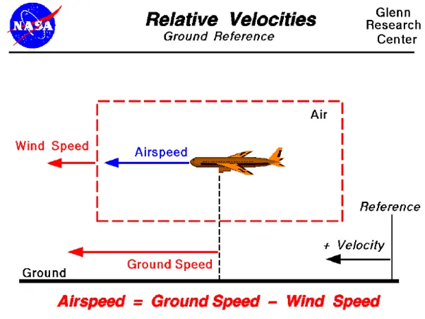
Air Speed is the speed of the aircraft relative to the air it is flying in which is also the speed at which the air flows across the aircraft wings. Air speed determines whether there is enough air flow around the aircraft to make it fly.
- Ground speed
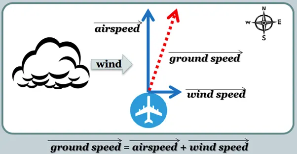
Ground speed is the speed of the aircraft relative to the surface of the earth. Hence it is the horizontal speed. Ground speed determines how fast an aircraft will reach the destination. Ground speed is the sum of the air speed and wind speed.
ANS 3:
Usually, the aircraft is pushed back to a safe distance from the terminal gate by using a tug vehicle. The tug vehicle is of small size with a high torque and mass.
The same operation can be done by using engine power for moving the aircraft backwards. This is done by using reverse thrust where the blades of the propeller are twisted to take the air from behind the aircraft. This could take a lot of engine power and is hazardous for personnel and equipment. The reverse thrust could cause debris to blow and harm the ground staff or passengers waiting at the terminal gate. The debris could damage the engine and create a fire hazard. Reversing a huge aircraft is very difficult. Hence reversing is done using a tug vehicle to a safe place and then the plane will use its own power to move the plane to the start of the runway.
ANS 4:
Once the clearance is obtained from the flight control, the aircraft is pushed back from the terminal gate by means of a tug vehicle. By so doing the aircraft is pushed away to a safe place before the engine can be turned ON. This is because there are several dangers that can exist when the aircraft uses the thrust from the jet engine for movement in the ground. Once the aircraft is away from the potential danger hazardous zone, the flight is now ready for taxiing. The engine of the aircraft is then turned ON. The aircraft then moves on its own power, the propulsive power that the jet engine produces for thrust during flight and moves on the ground. The aircraft then moves at a slow speed for safety reasons to the start of the runway. Sign boards and various types of light are used to guide an aircraft to the runway even if visibility is low. Tillers are used to rotate the front wheels to an angle of 45 degrees to steer the aircraft to the start of the run way. The aircraft is now ready to take off.
ANS 5:
Take-off:
During take-off the aircraft goes through a transition from ground on a runway to flying in the air. After taxing up to the starting of the runway, the aircraft is stopped. The engines are run at full power to check for engine related problems. The pilot then releases the brakes, when the aircraft is accelerated rapidly until the necessary speed for take-off is achieved. The take of speed varies depending on the weight of the aircraft, the density of air and aircraft configuration. The air density depends on the position of the airport from sea level and the atmospheric temperature. The required take off speed is to be achieved in case the aircraft has to take off which also depends on the length and slope of the runway.
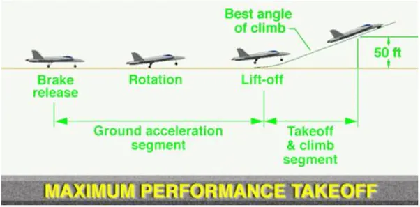
The take-off speed is relative to the motion of the air. In case of a head wind the take-off speed is much less as there is greater flow of air over the wings. Hence the aircrafts usually take off against the wind. Side wind is usually not preferred as this could disturb the stability of the aircraft. The take-off speeds for the jetliners are usually 240 to 285 Km/hr and is directly proportional to the weight of the aircraft. Some aircraft have difficulty in generating enough lift during take-off. In such cases they are fitted with high lift devices which includes slats and usually flaps which increases the camber of the wings which creates more lift at low speeds. Just after the climb phase, the wheels are retracted into the aircraft and undercarriage doors are closed making the aircraft more aerodynamic.
TYRE DESIGN:
Tyre is an integral component of an aircraft in terms of safety. Tyres help to absorb the shock of landing and provides cushion. It also provides the necessary traction for braking and stopping the aircraft.
The aircraft is designed in such a way that the aircraft will be able to withstand extremely heavy loads while landing, take off, taxing and parking. The number of wheels required for aircraft increases with the weight of the aircraft as the weight of the aircraft needs to be more evenly distributed
ROLLING RESISTANCE
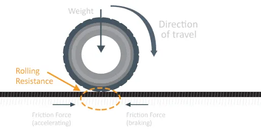
Rolling resistance is the force that resists the motion when the body rolls on the surface.
It is represented by the following equation:
Frr = μr m g
Where ,
Frr = rolling resistance force (N)
μr = coefficient of rolling resistance
m = Total mass of the vehicle (kg)
g = Acceleration due to gravity (m/s2)
BRAKING FORCES WHEN LANDING
Aircraft brakes helps to stop a moving aircraft by converting kinetic energy to heat energy by means of friction between rotating and stationary discs located in brake assemblies in the wheels. During landing these brakes provide critical stopping friction which enables the aircraft to stop within the length of the runway. In case of any technical snag the aircraft brakes help in stopping the vehicle before take -off.
Aircraft brakes also prevent motion of the aircraft when it is parked and limits the speed during taxing and can also help in steering the aircraft on the ground by applying different levels of braking force to the left and right-side brakes. Aircraft brakes work in conjunction with other brake mechanisms such as thrust reversers, air brakes and spoilers. Thrust reversers are surfaces which are deployed into the path of the jet blasts from the engine to redirect propulsive thrust in a direction which apposes the motion of the aircraft.
Air brakes and spoilers are flight control surfaces which create additional aerodynamic drag when deployed into the path of air flowing around the aircraft.
- TYRE PRESSURE:
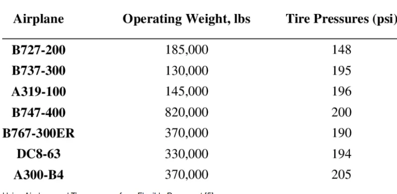
Aircraft tyres are designed in such a way that the tyre can withstand heavy loads for short duration of time. The number of tires required for aircraft increases with weight of the aircraft as the weight of the plane needs to be more evenly distributed. The thread pattern in the aircraft tyre is designed in such a way that it can facilitate stability in high crosswind conditions and also for braking effect. Tyres can get overheated if maximum amount of brake is applied in case of aborted take-off or emergency landing. The fuses provide a safer failure mode which prevents the explosion of tyres by deflating it in a controlled manner which helps in minimizing the damage to the aircraft and the objects in the surrounding environment. Aircraft tyres operate at high pressure up to 200 psi.
PART B:
ANS 6 A :
The following force and power required by the towing vehicle to push or pull the aircraft:
- Rolling resistance force
- Acceleration force
- Aerodynamic drag force
CALCAULATIONS:
Lets us assume an Aircraft.
Mass of the Aircraft (ma)=48500 kg
Mass of the towing Vehicle (ma1)=8000 kg
Thereor Total Weight of Towing Vehicle(m)=56500 kg
Coefficient of rolling resistance (μr) = 0.03
Acceleration due to gravity (g) = 9.81ms-2
Frontal area of an aircraft (A) = 85m2
Final velocity of the aircraft (vf) = 3m/s
Initial velocity of the aircraft (ui) = 0m/s
Coefficient of drag of an aircraft (cd) = 0.15
Density of air (ρ) = 1.225 kg/m3
Acceleration time of the aircraft (ta) = 10seconds
The speed of the Vehicle(V)=20Kmph
The speed of the Vehicle(V)=20*5/18=5.556 m/sec
ROLLING RESISTANCE FORCE:
Rolling resistance is the force that resists the motion when the body rolls on the surface.
It is represented by the following equation:
Frr = μr m g
Where ,
Frr = rolling resistance force (N)
μr = coefficient of rolling resistance
m = Total mass of the vehicle (kg)
g = Acceleration due to gravity (m/s2)
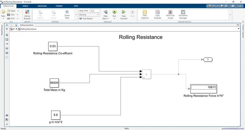
For the Aircraft :
Frr = μr m g
Frr = 0.03 x 48500 x 9.81
Frr (a) = 14259N
For the towing Vehicle:
Frr = μr m g
Frr = 0.03 X 8000 X 9.81
Frr (t) = 2352 N
We have to add mass of the Aircraft as the towing vehicle pushing or pulling the aircraft same time,therefore total Rolling Resistance force will be :
Total Rolling Resistance force
Frr =Frr(aircraft)+Frr(Towing Vehicle)
Frr =14259+2352
Frr = 16611N
AERODYNAMIC DRAG FORCE
Aerodynamic drag force is the drag force that acts apposite to the relative motion of any object moving with respect to a surrounding fluid.
It is represented by the formula:
Fd = ½ x ρ x A x cd x v2
Where,
Ρ = Density of air (kg/m3)
A = Frontal area ( m 2)
cd = Drag coefficient
v2 = Velocity (m/s)
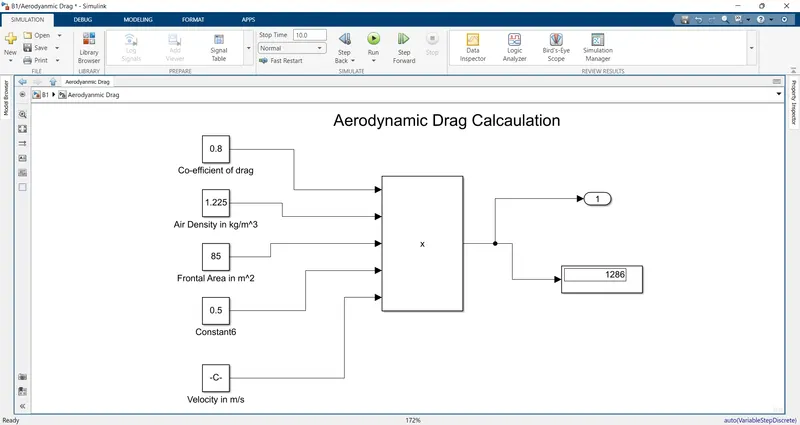
Aerodynamic Drag Force:
Fd = ½ x ρ x A x (cd(Aircraft) +cd(Towing Vehicle)x v2
Fd =1/2x1.225x85x(0.15+0.65)x 5.562
Fd = =1286N
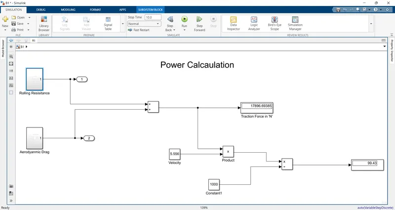
Total Force of the towing Vehicle:
F=Fad +Frr(Vehicle)
F=1286+16611
F=17897N
Power Required:
P = F x V
p=17897 x 5.55
P=99.43KW
ANS 6 B :
Develop the model for the calculated force and power using Simulink.
ANS 7:
ANS 7 A :
The following are the assumed parameters:
AIRCRAFT PARAMETERS
|
PARAMETERS |
VALUES |
UNITS |
|
Mass of the aircraft |
48500 |
kg |
|
Coefficient of rolling resistance |
0.03 |
-- |
|
Frontal area of the aircraft |
85 |
M2 |
|
Final velocity of the aircraft |
3 |
m/s |
|
Initial velocity of the aircraft |
0 |
m/s |
|
Coefficient of drag of an aircraft |
0.15 |
-- |
|
Acceleration time of the Towing vehicle |
10 |
Seconds |
TOWING VEHICLE PARAMETERS
|
PARAMETERS |
VALUES |
UNITS |
|
Mass of the Towing vehicle |
8000 |
kg |
|
Coefficient of rolling resistance |
0.013 |
-- |
|
Frontal area of the Towing vehicle |
8 |
M2 |
|
Final velocity of the Towing vehicle |
3 |
m/s |
|
Initial velocity of the Towing vehicle |
0 |
m/s |
|
Coefficient of drag of the Towing vehicle |
0.60 |
-- |
|
Acceleration of the Towing vehicle |
10 |
seconds |
|
Gear ratio |
10 |
The total power required to push or pull the aircraft by the towing vehicle is 97.022952KW and the total tractive force is 32340.984N. To calculate the torque required by the Towing vehicle the following parameters are assumed as shown above:
T = Fr * r /G
T = 32340.984 * 0.4 / 10
T = 1293.63 Nm
The torque required for towing the vehicle to push or pull the aircraft is 1293.63 Nm
To design the electric power train of the towing vehicle a motor is selected based on its power rating and the battery required based on energy requirement and duty cycle range to control the aircraft speed from zero to highest.
MOTOR
The motor is selected with a power rating of 97.022KW and torque of 1293.63 Nm . TECO IE2 electric induction motor is selected which has a power output of 110 KW and torque at full load is 1420Nm that satisfies the power output and torque needed for the vehicle.
MOTOR SPECIFICATIONS
Output power – 110 KW, 150 hp
Full load speed – 740 rpm
Full load Efficiency – 94.5%
Full load current – 210A
Full load Torque – 1420 Nm
Rated voltage – 400V/50 Hz
DUTY CYCLE
The rated voltage is 400V and the current is assumed to be 250A. So, the input power of the motor is calculated as product of voltage and current.
Pi = V * I
Pi = 400 *280
Pi = 112000W
Pi = 112KW
To calculate the duty cycle we divide output power to input power
P = Po / Pi
P = 97.02 / 112
P= 0.866
P= 86%
ENERGY
To calculate the energy required from batteries or battery pack. The energy is obtained by multiplying the output power and time. Assuming the battery usage for 5 minutes is 300 seconds.
E = Po * t
E = 97.02 * 300
E = 29106kJ
So, the battery pack provides 29106 KJ of energy to the vehicle. Since the battery are rated in kilowatt hour (KWH). We have to convert KJ to KWH we divide it by 3600.
E = 29106/3600
E= 8.08KWH
So, the battery pack should provide at least 8.08 KWH to the vehicle.
POWERTRAIN DESIGN
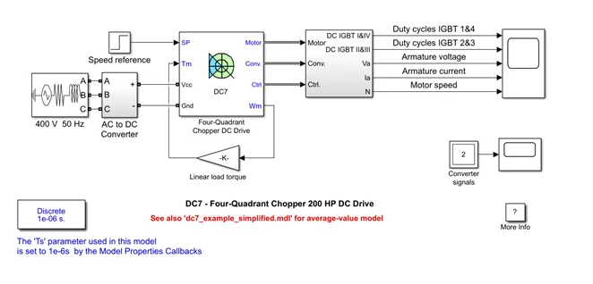
ANS 7 B :
EXCEL SHEET CALCULATIONS
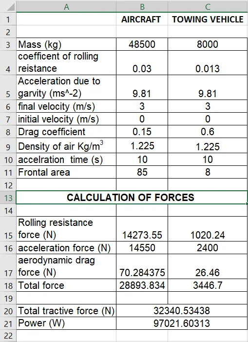
TOWING VEHICLE SIMULATION POWER TRAIN BLOCK DIAGRAM
RESULTS
|
Required torque output of the motor |
1293.63 Nm |
|
Input power of the motor |
112KW |
|
Duty cycle range |
86% |
|
Energy required from the batteries |
8.08KWH |