Week - 4
washing maching and Gear shift
AIM : using Stateflow chart Implement control logic of a “washing machine” and “Gear shift” process.
- Implement control logic of a “washing machine” using Stateflow as per given sequence:
- If the power supply is available, the system gets activated
- If the Water supply is not available, stop the process & indicate through LED
- Soaking time should be 200s followed by Washing time of 100s.
- Then rinsing happens for next 20s & dryer runs for 50s
- After all the processes have completed turn on the finished LED
SOLUTION :
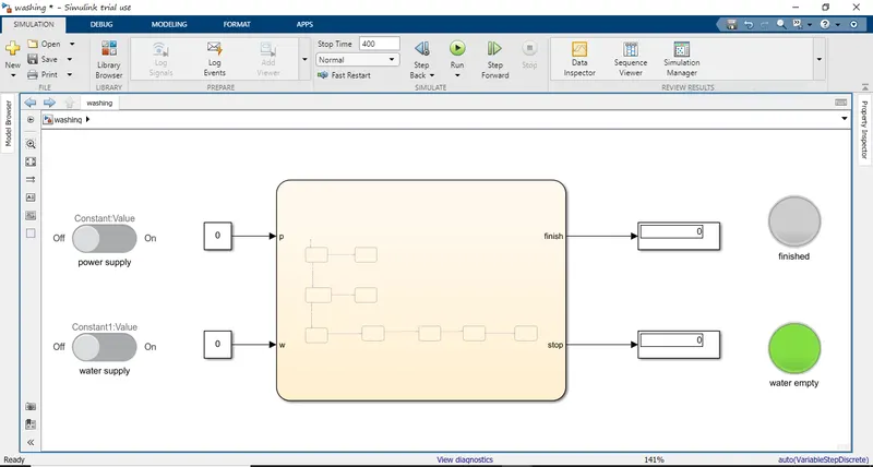
final view
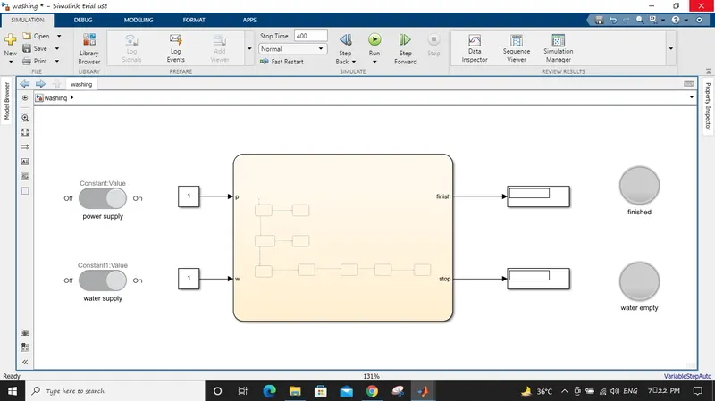
in the above figure
blocks used :
constant block: which represent as as a constant number 1 and and connected with sliding switch.
sliding switch : this block is connected with the constant no when the switch is off the constant number goes 0 and when switch is on constant no goes 1.
display : output value is shown in display which is connected with lamp.
lamp: lamp is link to display when the lamp show the value 1 or 0 it turns on and off accordint to it is set.
here lamp is given condition first lamp when it is 1 then it will turn on
and second lamp when it is 0 then it wll turn on.
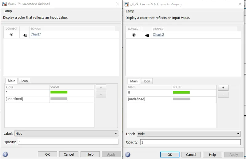
INSIDE VIEW
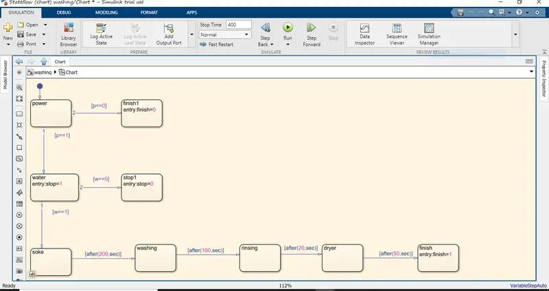
EXPLANATION :
1] power to finish with the condition [p==0] means when the power switch is off then
finish1 block will show 0 in the finish display .
2] power to water with the condition [p==1] means when the power switch is on then ith will go to water block.
3] water to stop with the condition [w==0] means when the water switch is off then
stop block will show 0 in the stop display . and the led will be on
4] water to soke with the condition [w==1] means when the water switch is on then it will to to the soking block.
soking to washing after(200,sec) which is a delay command.
washing to rinsing after(100,sec) which is a delay command.
rinsing to drying after(20,sec) which is a delay command.
drying to finish after(50,sec) which is a delay command.
when process reach to the final finish block the finish display will show 1 and the led will get on.
WORKING
when the power switch is on and water switch is on the constant block gives 1 value and according to the condition it finish block show 1 and the lamp start glowing.
and stop block is show 1 {due to the condition of water empty lamp is given 0} so the water lam will not glow.
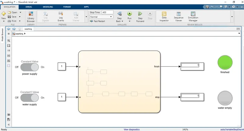
when the power switch is off and water switch is off the constant block gives 0 value and according to the condition in finish block show 0 and the finish lamp will glowing.
and stop block is show 0 {due to the condition of water empty lamp is given 0 } so the water lamp will start glow.
QUESTION 2
2. Make a Simulink chart for the “Gear shift” logic as per below conditions:
Speed Range(kmph) Gear
0 to 15 1
16 to 25 2
26 to 40 3
41 to 60 4
Above 61 5
Give speed input while the simulation is running & display the gear number.
SOLUTION:
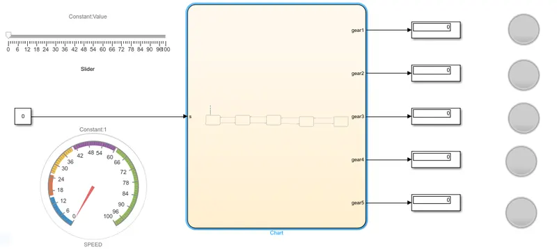
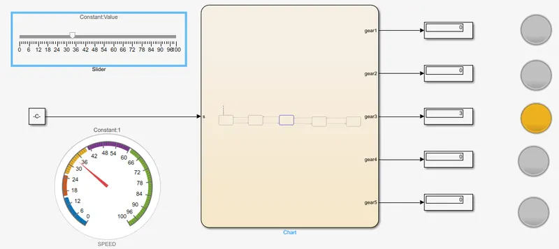
block used
slider : a scale which can be moved front and back manually which gives the value when connected.
constant: gives constant number output . here it is connected with slider.
gauge: show the value in dial gauge according to the value change in the constant.
display: shows the output value of gears.
lamp: turn on and off according to the condition given when connected to display.
FINISHED VIEW
inside view of flowchart
explanation of gear setup
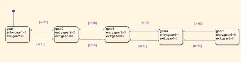
first block represent gear1 where [=1] means it will show the value of gear1 as 1 in display and condition is given to go in other block is when the s>15
and exit gear1 where [=0] is when the gear1 shift to the gear2 the gear1 will show 0 in the display
second block represent gear2 where [=2] means it will show the value of gear2 as 2 in display and condition is given to go in other block is when the s>25
and exit gear2 where [=0] is when the gear2 shift to the gear3 the gear2 will show 0 in the display
third block represent gear3 where [=3] means it will show the value of gear3 as 3 in display and condition is given to go in other block is when the s>40
and exit gear3 where [=0] is when the gear3 shift to the gear4 the gear3 will show 0 in the display
fourth block represent gear4 where [=4] means it will show the value of gear4 as 4 in display and condition is given to go in other block is when the s>60
and exit gear4 where [=0] is when the gear4 go to the gear5 the gear4 will show 0 in the display
fifth block represent gear5 where [=5] means it will show the value of gear5 as 5 in display
and exit gear5 where [=0] is when the gear5 go to the gear4 the gear5 will show 0 in the display where the condition is given as s<60
WORKING:-
{the running time is inf which is infinity }
a constant block is given to the chart as input which denotes the [s] as speed this constant block is connected with slider which is having range from 0 to 100.
also the constant block is connected with the gauge.
in output evert block of gear is connected with the display and each display connected with seprate lamp .
now,
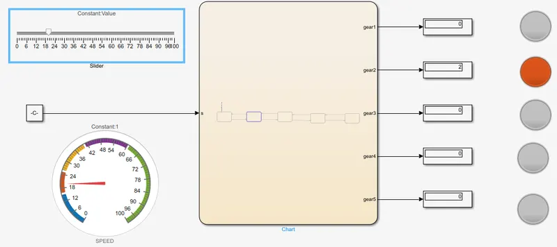
when the slider is moving from 0 to 15 the constant block which represent it in gauge and also give the value to the gear1 which will show 1 in display. and the lamp 1 will be on
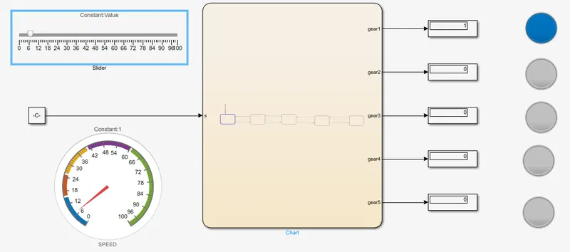
when the slider is moving from 16 to 25 the constant block which represent it in gauge and also give the value to the gear1 ,gear2 which will show 2 in display2 and 0 in display1 and the lamp 2 will be on and lamp 1 will go off.
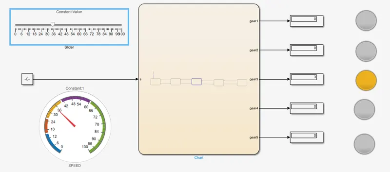
when the slider is moving from 26 to 40 the constant block which represent it in gauge and also give the value to the gear1 ,gear2,gear3 which will show 3 in display3 and 0 in display1,display2 and the lamp 3 will be on while lamp 1,2 will go off.
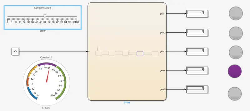
when the slider is moving from 41 to 60 the constant block which represent it in gauge and also give the value to the gear1 ,gear2,gear3,gear4 which will show 4 in display4 and 0 in display1,display2,display3 and the lamp 4 will be on while lamp 1,2,3 will go off.
when the slider is moving above 61 the constant block which represent it in gauge and also give the value to the gear1 ,gear2,gear3,gear4,gear5 which will show 5 in display5 and 0 in display1,display2,display3,display4 and the lamp 5 will be on while lamp 1,2,3,4 will go off.
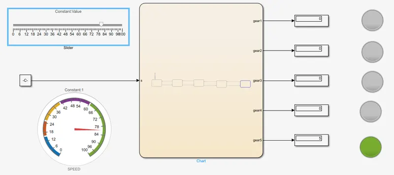
as the slider will slide in reverse direction the process will work in reverse direction and show .
thank you