Week - 4
AIM:
To create a Simulink model of the Washing machine by implementing the logic in chart block and create a Gear shift logic by using chart block in Simulink.
OBJECTIVES:
- Implement control logic of a “washing machine” using Stateflow as per given sequence:
- If the power supply is available, the system gets activated
- If the Water supply is not available, stop the process & indicate through LED
- Soaking time should be 200s followed by Washing time of 100s.
- Then rinsing happens for the next 20s & dryer runs for 50s
After all the processes have been completed turn on the finished LED.
2. Make a Simulink chart for the “Gear shift” logic as per the below conditions:
Speed Range(kmph) Gear
0 to 15 1
16 to 25 2
26 to 40 3
41 to 60 4
Above 61 5
Give speed input while the simulation is running & display the gear number.
SIMULINK MODEL:
1)
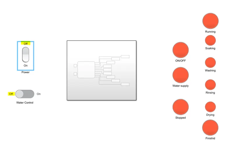
The washing machine has many states like Washing, Soaking, Rinsing, Drying. These all states are going to be run if power and Water supply are present there. So we model a Simulink model of logic of a Washing machine by using a Stateflow chart in Simulink.
The created logic of the Washing machine in Simulink :
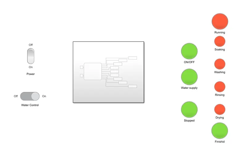
this is the Simulink program looks from the outer. But it has a subsystem which has the main core part of the Simulink model.
Subsystem;
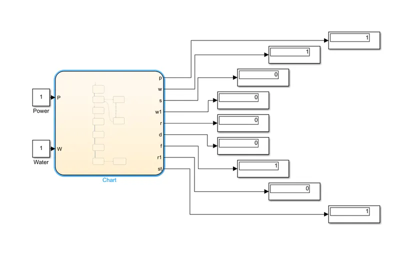
Inside chart;
Simulink model link :
Current version:
Previous version:
EXPLANATION AND RESULTS:
This logical system of the washing machine is created in such a way that indicates each process in the dashboard when only the power and water supply is ON otherwise it's stopped and indicates which is OFF in red color LED.
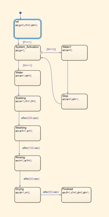
We can see the logic of this program inside the chart block. where I take one reference block as ref and followed by the main blocks.
- Block after the ref block is called System_Activation block which gives an output of p is equal to 1 only if the power is ON([P==1]).
- After the Systerm_Activation block, we have a Water block that gives an output of w is equal to 1 if only the water supply takes place ([W==1]) and also give another output of st which is equal to 0(for turn off the 'stopped' display LED in the dashboard.
- The next block is called the Soaking block which gives an output of s=1,r=1 and f=0 for the processed signal of the washing machine are Soaking, Running and not finished.
- The Washing block is only activated after 200 sec to the previous block. this condition is provided in between the block at the flow arrow.
- when the Washing block is activated, it gives an output of w1=1 to initiate the indication of washing state and s=0 for turning off the Soaking state signal.
- After 100 sec the Rinsing block will activate and gives an output of r=1 to initiate the rinsing state signal in the dashboard and w1 = 0 to stop the signal of the washing state.
- After 20 sec Drying block will activate and gives d=1 and r=0 to initiate the drying signal and stop the signal of rinsing.
- After 50 sec the final block 'Finished' will be activated and it gives f=1 for finish status and st=1 for the machine is stopped and turn off the signal of d and r1(drying and running)
It will be much smoother and better if we run it slow speed for some particular time that we want.
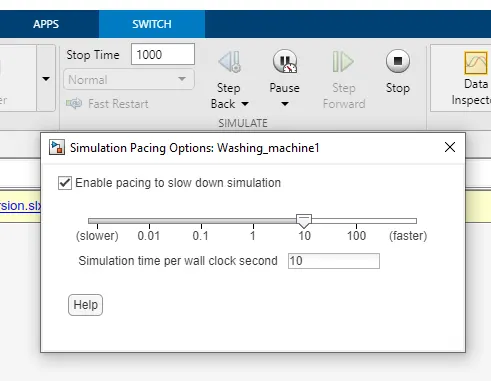
view of each state at the Dashboard is given below;
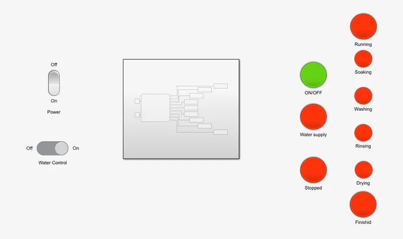
at the start, the power indicator 'ON/OFF' Turns on when the power is on.
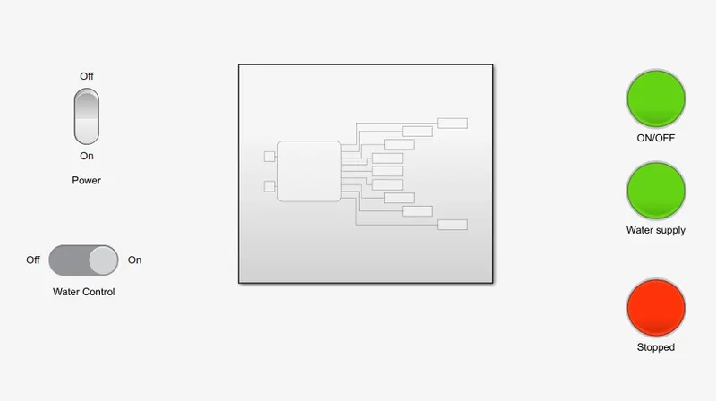
if the water supply on LED shows a green light.
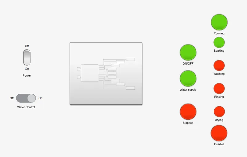
After the power and water supply are checked, the Running LED is turn Green and simultaneously the soaking LED to indicate the process state for 200 sec.

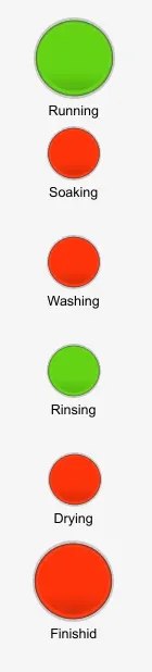
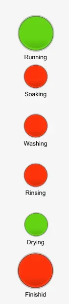
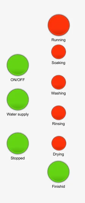
for 100sec for 20sec for 50 sec After finishing the Drying process
What happens if the water or power is off or both?......
if anyone or both are in OFF state, the machine won't run and indicates through LED in Dashboard. we will see what happens if the power is in OFF condition.
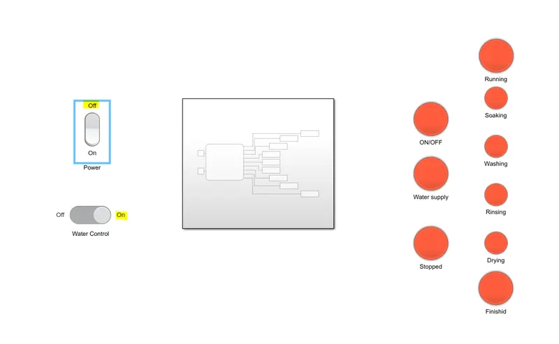
When the Water supply is in OFF condition.
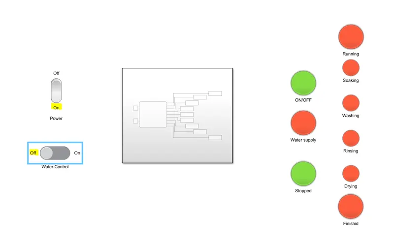
When both conditions are in turn-off condition.
2)
Created Simulink Stateflow chart for the “Gear shift” :
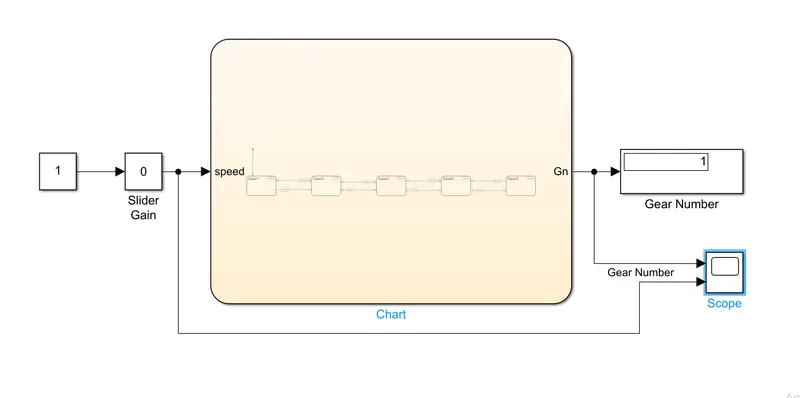
Here we have one constant which is connected to the Slider Gain block and followed by Chart and one Display block(Gear number). the scope block is used to store the results.
The slider Gain block is responsible for changing the speed input of the Chart block while this program is running.
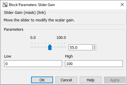
We set the slider limit as 0 to 100 which is nothing but the speed input to Chart.
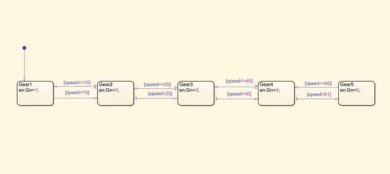
when we go inside the chart, it will be like;
Simulink model link :
Current version:
Previous version:
EXPLANATION AND RESULTS:
- When the input speed is o to 15 the Gear state will be 1 as per the condition.
- If the speed of the input goes higher than 15, The Gear will be shifted to 2 automatically.
- For Gear shifts of 3, 4 and 5 happen when the speed input will greater than 25,40 and 61.
- If we reduced the speed input, The Gear shifted to 4, 3, 2 and 1 when the corresponding speed condition meets.
- Record all the output and inputs with the help of the scope block.
Results of Gear number at different speed is given below;
we have to run it continuously, so the stop time will be 'inf'.
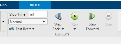
while the program is running, I changed the input value from 0 to 100 and then from 100 to 0 back to check the results which is given below;
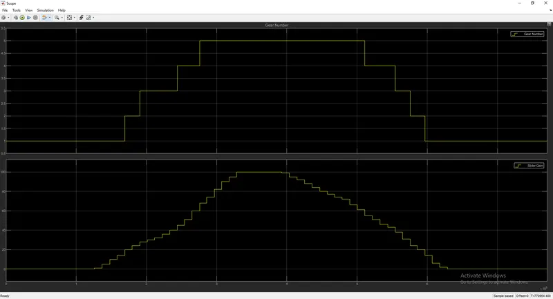
Hence, this graph shows that the Gear will change according to the speed input by the user
CONCLUSION:
Finally, The logic mechanism of the Washing machine and the Gear system as per the given condition was made and got the results successfully.
REFERENCE:
- https://www.youtube.com/watch?v=657hjCj_xLQ
- https://in.mathworks.com/help/stateflow/gs/stateflow-charts.html#:~:text=A%20Stateflow%C2%AE%20chart%20is,%2C%20and%20time%2Dbased%20conditions
- https://in.mathworks.com/help/stateflow/ug/common-modeling-errors-the-debugger-can-detect.html
- https://in.mathworks.com/help/stateflow/ug/stateflow-edit-time-checks.html