Week - 4
Simulink for ELECTRICAL and MECHANICAL Engineer
Challenge – 4
Q 1. Implement control logic of a “washing machine” using Stateflow as per given sequence:
- If the power supply is available, the system gets activated
- If the Water supply is not available, stop the process & indicate through LED
- Soaking time should be 200s followed by Washing time of 100s.
- Then rinsing happens for next 20s & dryer runs for 50s
After all the processes have completed turn on the finished LED.
Answer :
Objective : To implement control logic of a “washing machine” using Stateflow as per given sequence:
Theory :
Washing machine
A washing machine (laundry machine, clothes washer, washer, or simply wash) is a home appliance used to wash laundry. The term is mostly applied to machines that use water as opposed to dry cleaning (which uses alternative cleaning fluids and is performed by specialist businesses) or ultrasonic cleaners. The user adds laundry detergent, which is sold in liquid or powder form, to the wash water.
The earliest washing machines simply carried out a washing action when loaded with clothes and soap, filled with hot water, and started. Over time machines became more and more automated, first with very complex electromechanical controllers, then fully electronic controllers; users put clothes into the machine, select a suitable program via a switch, start the machine, and come back to remove clean and slightly damp clothes at the end of the cycle. The controller starts and stops many different processes including pumps and valves to fill and empty the drum with water, heating, and rotating at different speeds, with different combinations of settings for different fabrics.

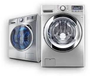
A washing machine is a machine used to wash various types of clothes without applying any physical effort. With a washing machine, I don’t have to rub clothes with my hand or squeeze them to remove the water from them. The washing machine is also called a cloth washer or simply a washer. The washing machine enables to wash clothes automatically without having to supervise its operation. All you have to do is put the clothes in the machine and select the wash mode. The washing machine automatically takes in the amount of water and detergent required and it also automatically sets the timer for washing, rinsing and drying as per the selected mode of wash and the number of clothes to be wash.
Stages of washing :
There are mainly 4 different stages of a washing which helps in turn helps you to understand better and pick the option depending on the basis of your need successfully.
- Pre wash (soaking)
- Washing
- Rinsing
- Spinning
Learning these stages more frequently to understand the right option of washing at the right time.
Prewash (Soaking)
The option called prewash indicated filling the drum with a certain water level and mix up with the detergent powder. All this option helps to wash out all the stains including the stubborn or dirt very well from the clothes. This is possible as we soak the whole clothes placed into the drum. Finally, drain the water without making a second thought.
Taking the amount of water is different for both front load and top load washers respectively. In the front-load washing machines, it is all up to the settings done by the single user. Whereas at the top load washers, there are water level sensors for filling the drum at a certain level and clean the entire load getting rid of stubborn stains successfully.
Washing
At the particular time, the machine uses agitation which is for mixing both water and detergent, in turn moving the clothes all around the drum. Generally, the top load washing machines come with an agitator or impeller placed at the centre of the tub.
While coming to front- load washers, it depends upon the entire tub provided for enhancing better wash and clean the load ultimately. Moreover, the duration taken to complete the wash cycle is depends upon the settings option chosen by the user. Always the heavy load enhances high duration. Small or limited load enhances less duration.
Rinsing
The option called rinsing is known for the multi-talented option. During this particular cycle is on the flow, the soapy water taken from the clothes. And all the fresh or pure water is sparkled to the clothing available in the tub. This particular rinse option held responsible for taking soapy water out of the washer without facing any kind of difficulties. Finally, the agitation with plain water is considered the last step in the rinsing option.
Spinning
Spinning is done to dry the entire clothes before getting to the end of the actual wash cycle. And this several washing machines are going to be spun at different needs. In turn, the speed of one particular spin is calculated in revolutions per minute(rpm) respectively. This indicates the speed of the spin extracting the whole amount of the water from the clothes making it dry very well.
These are the different cycles done by each model available in the Indian market. Accordingly, the machine coming with these factors enhances high performance. All the things one should aware of these options and must pick the right option at the right time. For any doubt, mention a single comment in the following rectangular section.
Modelling of washing machine in Simulink :
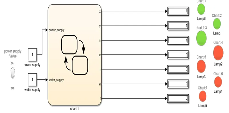
This is the Stateflow-Simulink model for washing machine designed for operating under certain given conditions:
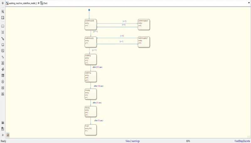
And this is the Stateflow model designed or coded with that condition which helps the model to run particularly at the right time.
These are the following things we need for modelling the subsystem of washing machine logical block settings:
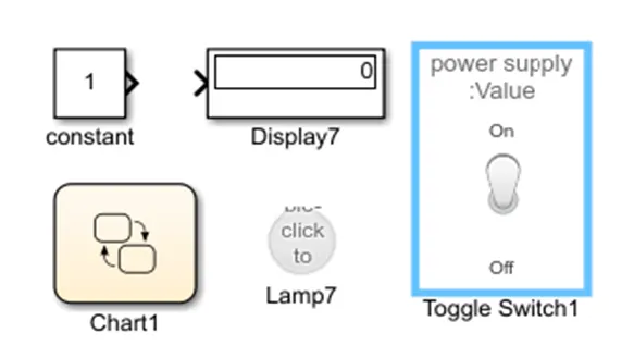
- Toggle switch
- Constant
- State flow chart
- Lamp
- Display
Observation :
Now the following steps involves in the process we go step to step:
- Switched OFF when non operational condition.(all lamps glow red)
- Power supply given to machine.( Lamp 6 glow)
- Water supply given to the machine.( Lamp 1 glows green)
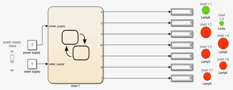
- Soaking action command given at certain time interval for 200 seconds.( Lamp7 glows green)
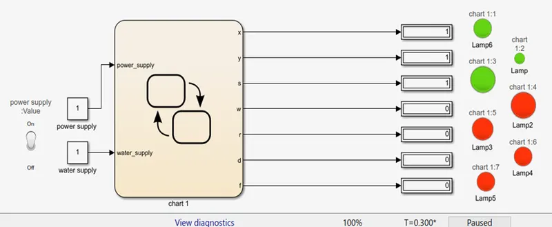
- Washing command given after soaking for 100 seconds.( Lamp2 glows green)
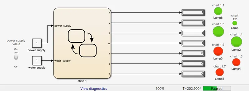
- Rinsing command given to machine after washing, it analyse and starts rinsing the clothes for 20 seconds.(Lamp3 glows green)
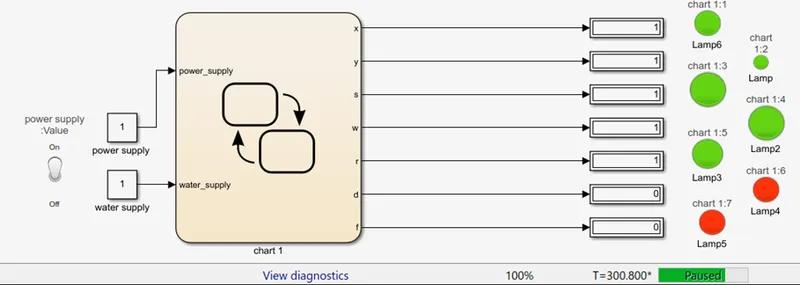
- Drying command action takes place when rinsing process is done for 50 seconds.(Lamp4 glows green)
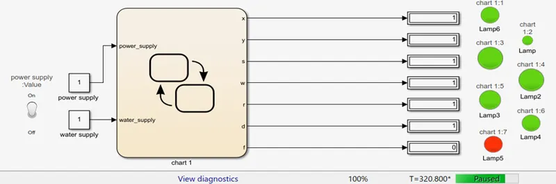
- Finally, end the process of all command of action and all the lamps glow green.(Lamp5 glows green)
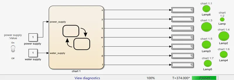
Conclusions :
Just accordingly to given every condition, I tried to define all the terms and also tried to execute this model as per the given conditions. Hopefully, this model runs and give me the all desired output that I want.
-----------------------------------------------------------------------------------------------------------------------------
Q 2. Make a Simulink chart for the “Gear shift” logic as per below conditions:
Speed Range(kmph) Gear
0 to 15 1
16 to 25 2
26 to 40 3
41 to 60 4
Above 61 5
Give speed input while the simulation is running & display the gear number.
Answer:
Objective;
To create a state flow chart for the “Gear Shift” in the Simulink as per the below conditions given :
Speed Range(kmph) Gear
0 to 15 1
16 to 25 2
26 to 40 3
41 to 60 4
Above 61 5
Theory :
To effect a gear change, selecting first gear, for example, the driver depresses the clutch, disengaging the input shaft. Using the shaft lever, the driver selects the first gear, and the linkage moves the shift fork to connect the 1st-2nd locking collar with 1st gear, locking it to the output shaft. Now, when the clutch is released, engaging the input shaft, the output shaft turns because 1st gear is locked to the output shaft by the locking collar.
As the driver speeds up, selecting 2nd gear simply involved repeating the process, but moving the shift lever to 2nd gear. The shift shaft moves the shift fork to disengage 1st gear and engage 2nd gear. Releasing the clutch engages the input shaft again, this time routing power through 2nd gear. Changing to 3rd gear involves using a second shift linkage, shift fork and locking collar, this one between 3rd and 4th gears.
Because the countershaft and output shaft turn at different speeds, moving from 1st to 2nd gear, trying to engage a higher gear while the vehicle is moving slower would be like trying to turn the shaft at two different speeds, which is impossible. Synchronizer rings are like tiny clutches, using friction to bring the locking collar and the gear to the same speed, at which point they easily mesh and power can be reapplied.
Before I go into the Simulink for the transmission box simulation need to follow the below conditions for the below conditions for the setup.
Observation:
Speed Range(kmph) Gear
0 to 15 1
16 to 25 2
26 to 40 3
41 to 60 4
Above 61 5
And by doing so I do that in a coded pattern in the state flow chart which I have mentioned below:
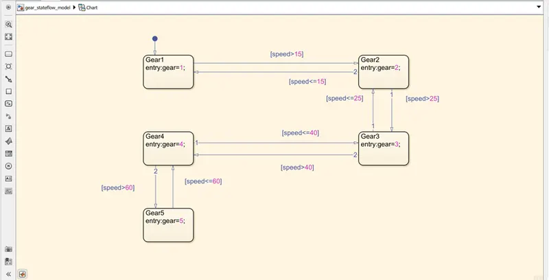
These are the followings block sets that I used for creating this model above shown :
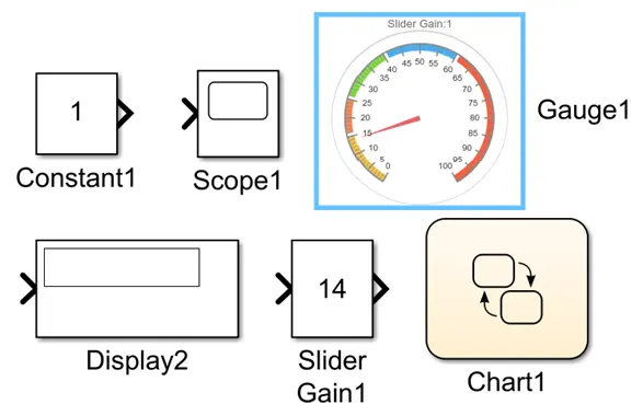
- State flow chart
- Slider gain
- Constant
- Display
- Lamps
This is the final staeflow model for gear shift logic system.
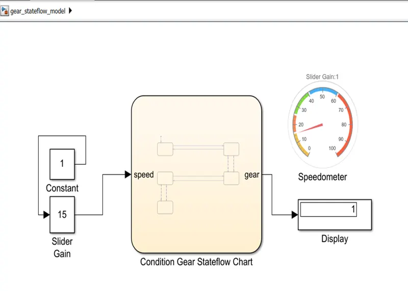
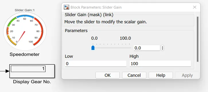
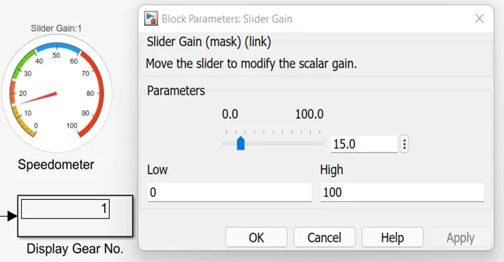
This is Simulink model of gear system at different speed conditions (as shown in the speedometer and slider gain parameter window).
- When speed is just 0 (no speed condition), gear should be in no. 1 to start a vehicle atleast.
- When the speed ranges upto 15 km/h, gear remains unchanged in no. 1.
- When the speed starts from 16 km/h, gear changes from 1 to 2.
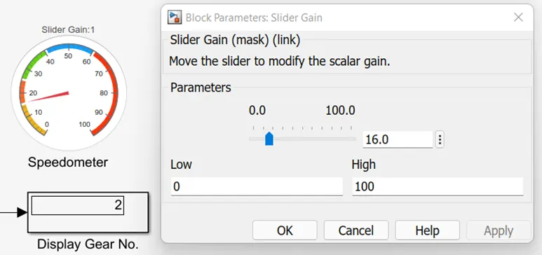
- When the speed ranges upto 25 km/h, gear remains in number 2.
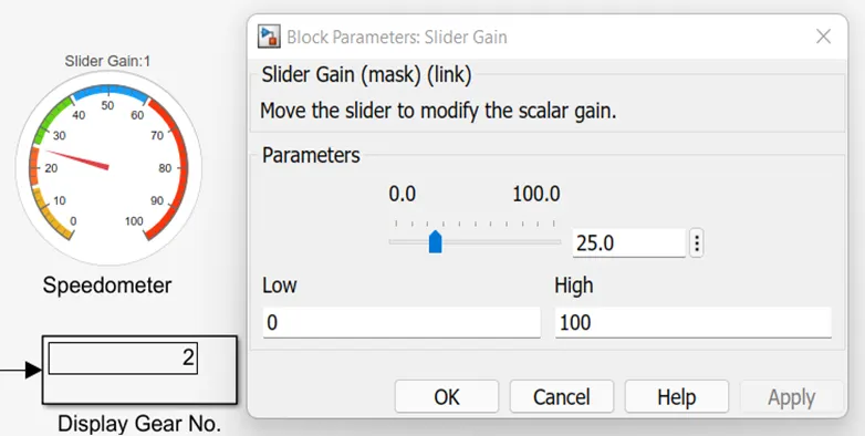
- When the speed ranges from 26 km/h, gear changes from 2 to 3.
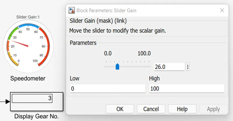
- When the speed ranges upto 40 km/h, gear remains in number 3.
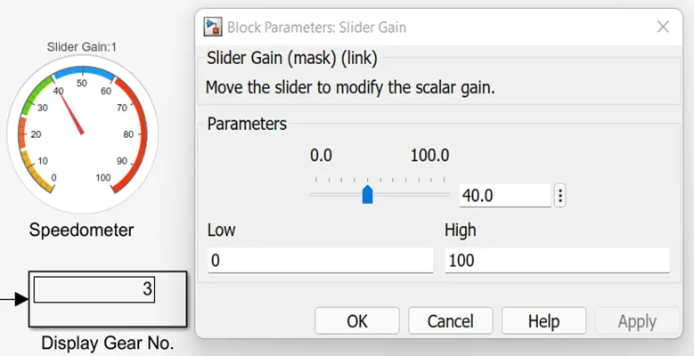
- When the speed ranges from 41 km, gear changes from 3 to 4.
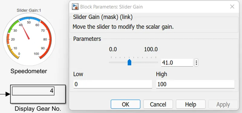
- When the speed ranges upto 60 km/h, gear remains unchanged in number 4.
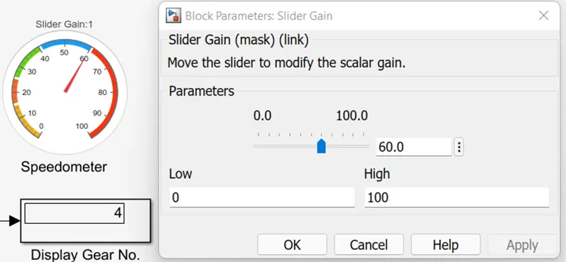
- When speed ranges from 61 km/h, gear changes from 4 to 5.
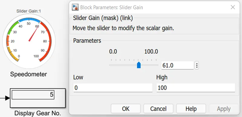
- When the speed ranges upto 100 or just more than 61 km/h, the gear value remains unchanged in number 5.
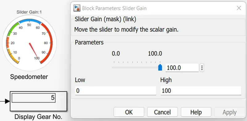
And the all the output is just as similar as it is shown above in the other speed conditions.
Conclusion :
So this is model that I create and run for this particular time period and that’s how I did the gear shift logic in the Simulink. As I can see that the lamp is glowing according to the gear relation conditions and it shows here and the gear is at the currently running according to the speed condition given in the question using slider gain.