Week-6 Challenge: EV Drivetrain
Introduction to Hybrid Electric Vehicle using Matlab and Simulink
Challenge-6
Challenge : EV Drivetrain
1. Which types of power converter circuits are employed in electric and hybrid electric vehicle?
Introduction to Power Converter:
Powe converter is a kind of electronics technology that deals with processing and controlling the flow of electrical energy in order to supply voltages and currents in a form that optimally suited for end user’s (customers)requirements. A power electronics converter uses power electronic switch components i.e. transistors such as SCRs, TRIACs, IGBTs etc to control and convert the electric power into control signals. The main aim of the converter is to produce conditioning power signal with respect to a certain application.
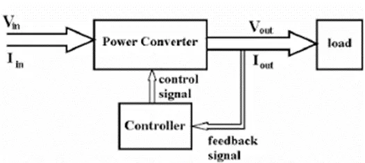
The power electronics circuit consists of both power part and control part. Power part transfers the energy from source to load and it consists of power electronics switches (SCR or TRIAC), transformers, electric choke, capacitors, fuses, ballast, regulators and sometimes resistors.
The control circuit or block regulates the elements in the power part of the converter. This block is built with a complex low power electronic circuit that consists of either analogy (continuous) or digital circuit (discrete). Power electronics converters perform various basic power conversion functions. This converter is a single power conversion stage that can perform any of the functions in AC and DC power conversion systems. Depending on the type of function performed by the converters, power converters are categorized into the following types:
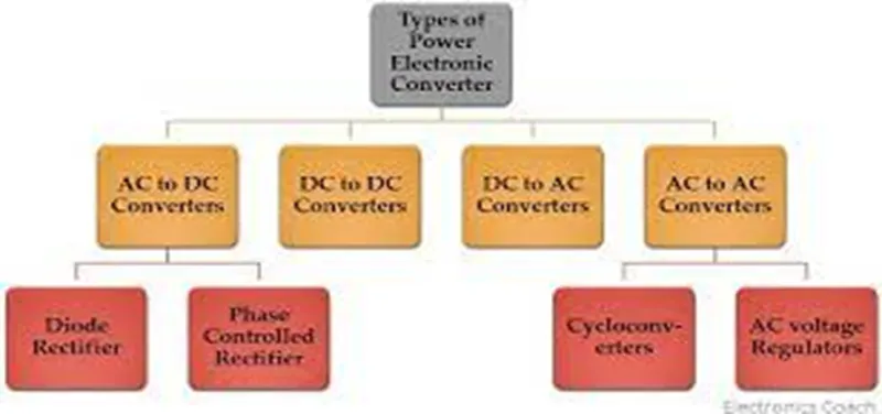
- AC to DC = Rectifiers are used to converts AC signal into pulsating DC signal.
- DC to AC = Inverters are used to convert DC signal into AC signal and give supply to respective connections as per the requirements.
- DC to DC = Chopper is a kind of filter circuit in bridge formation which is used to step-up or step-down the variable DC signal into constant Dc signal and supply to the respective users.
- AC to AC = Cycloconverter is used to converts the AC signal of desired frequency or desired voltage magnitude from a line AC supply.
These types of power electronics converters may be found in a wide variety of applications but among them only three types of power converter circuits are employed in electric and hybrid electric vehicle. The following power converter circuit are discussed below:
1. AC to DC converters or Rectifiers:
AC to DC converter is also called rectifier, which converts AC supply from main lines to DC supply for the load. The block diagram of AC to DC converter is shown in figure below.

The essential components in this rectifier include transformer, switching unit, filter and a control block.
Here, transformer adjusts the primary AC source supply to the input of rectifier. Usually, it is a step-down transformer that reduces the supply voltage to a circuit operating range.
The rectifier converts the low voltage AC supply into DC supply. It comprises diode and/or thyristors based on type of rectifier. The output of the rectifier is of pulsed DC and hence it is filtered using filter circuit, which is usually made with a capacitor or ac choke.
The control block controls the firing angle of thyristors in case of phase control rectifiers. Since the diode is not a controlled device, control block is not needed in case of diode rectifiers.
Rectifiers are majorly classified into two types:
- Uncontrolled Rectifiers/ Converter.
- Controlled Rectifiers/ Converter.
I. Uncontrolled Rectifiers:
This type of rectifier converts Ac voltage from mains into a fixed DC voltage.
Since the diodes are uncontrolled components (which do not require any triggering), these converters are called as uncontrolled converters as they produce a fixed voltage. The input voltage can be either single phase or three-phase. The diode rectifiers are classified into following types:
a. Single Phase Half-Wave Rectifier:
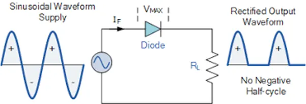
This type of rectifier is that which rectify only half cycle of the waveform. This article describes the half wave rectifier circuit working. The half rectifier consist a step down transformer, a diode connected to the transformer and a load resistance connected to the cathode end of the diode. The circuit diagram of half wave transformer is shown below:
The main supply input voltage Vin is given to the transformer which will increase or decrease the voltage and give to the diode. In most of the cases we will decrease the supply voltage by using the step down transformer here also the output of the step down transformer will be in AC. This decreased AC voltage is given to the diode which is connected in series to the secondary winding of the transformer, diode is electronics component which will allow only the forward biased current and will not allow the reverse biased current to flow. From the diode we will get the pulsating DC and give to the load resistance RL.
b. Single Phase Centre-tapped Full-Wave Rectifier:
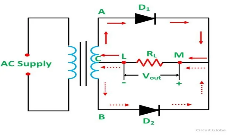
Centre tap is the contact made at the middle of the winding of the transformer. In the centre tapped full wave rectifier two diodes were used. These are connected to the centre tapped secondary winding of the transformer. Above circuit diagram shows the centre tapped full wave rectifier. It has two diodes. The positive terminal of two diodes is connected to the two ends of the transformer. Centre tap divides the total secondary voltage into two equal parts.
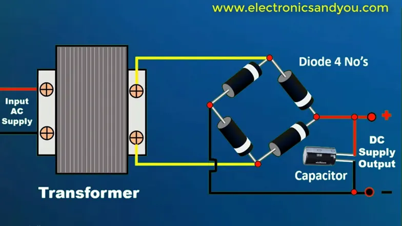
c. Single Phase Full-Wave Bridge Rectifier:
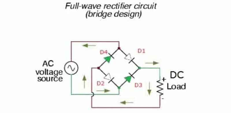
This rectifier consists of 4 diodes in its circuit. These are connected in such a way to form a bridge type structure (as shown in the figure) and a load in connected along with 4 diodes as shown below.
d. Three Phase Half-Wave Rectifier:
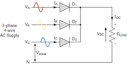
This rectifier consists of three diodes and its anode terminal are connected to three phase sources se Rring Y-Phase and . Du alteration of transformer as shown in the figure. The load is connected between the common cathode point and neutral terminal of star connected source.
When R-phase is at peak value, maximum conduct occurs through diode D1 as it is forward biased and no conduction takes place it during negative forward biased and no conduction takes place During Y-phase and B-phase maximum values, other two diodes conduct in a similar manner.
The main disadvantage of this rectifier is that the secondary winding consists of Dc component of current which can cause the transformer core to go under saturation problem. Therefore, it is not advisable to use three-phase half wave rectifier for large power applications.
e. Three Phase Full-Wave Rectifier:
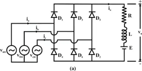
This type of rectifiers is suitable for high power applications, typically the power output higher than 15KW. The circuit of full-wave bridge is shown in figure below. It requires 6 diodes for the operation of the circuit. This type of circuit doesn’t need any neutral connection from three phase source therefore, a star as well as delta-connected sources can be used.
Here the output current flows through one diode of the upper group and one diode of lower group of diodes. If anode of a diode is at high potential, this upper group diode will conduct while other two diodes are reversed biased.
Similarly, the diode having the cathode at lower potential will conduct while other two diodes are off. The diodes pairs conduction for above circuit is given as D6-D1, D1-D2, D2-D3, D3-D4, D4-D5, D5-D6 and D6-D1 starts continuously to complete the cycle. Since one diode from upper group and one diode from lower group are always conducting together. Negative members of three phase voltages are rectified, so the output voltage consists of 6 segments of line voltage during one cycle. For this reason, three phase bridge rectifier also called 6 pulse rectifiers.
These are efficient rectifier as compared to half-wave converters. Due to 6 pulse output, ripple content in the output is very low, typically about 4.5%. This avoids the additional filter circuit in many high power applications. Even if a filter is required, a small sized filyer is enough because of increase in ripple frequency to 6 times the input frequency.
II. Phase Controlled Rectifier:
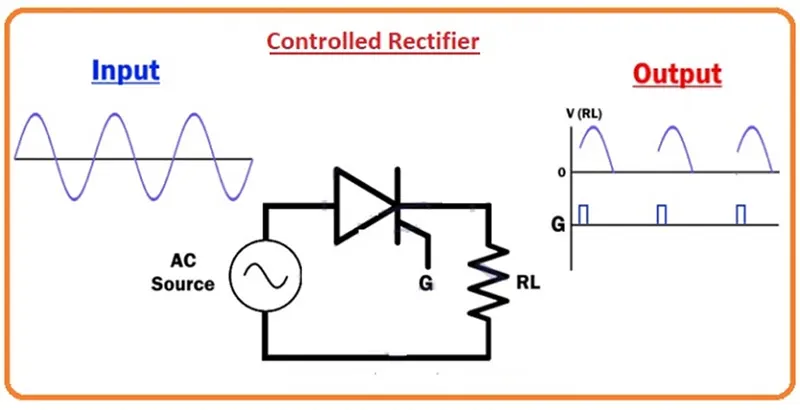
These are similar to the uncontrolled rectifiers but the only difference is that the uncontrolled diode are replaced by controlled thyristors family of devices such as SCRs. These are also called as phase controlled rectifiers. Unlike diodes, thyristors can be controlled by triggering them at desired instants in order to vary the output voltage.
The block diagram of a controlled rectifier is shown in the above figure that transfers the DC power to the load in a control manner by varying triggering angle of thyristors (by the control circuit) using different technologies such as a microprocessor or microcontroller based techniques. The start of thyristor conduction varies the average value of output voltage of the converter. Similar to the uncontrolled rectifiers types,
a. Single Phase Half-Wave Rectifier:
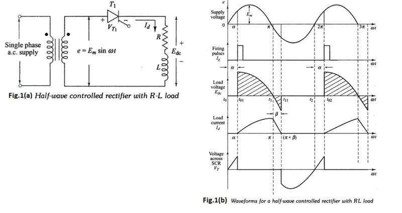
In this a single thyristor or SCR is connected between the secondary of the transformer and a resistive load as shown in figure. The primary of the transformer is connected to a single phase supply and consider that load is of resistive.
During the positive half cycle of the input Ac supply, thyristor T1 is forward biased and when it is triggered at some firing angle though gate terminal, starts conducting current to the load.
Since the SCR is a unidirectional device, it turns OFF during negative half-cycle. So the output voltage is produced only for positive half cycle.
The output power delivered by this half-wave rectifier is controlled by phase control, i.e, varying firing angle to the gate terminal. The load of this rectifier can be a RL load and Rfe load with free wheeling diode.
b. Single Phase Full-Wave mid-point rectifier:
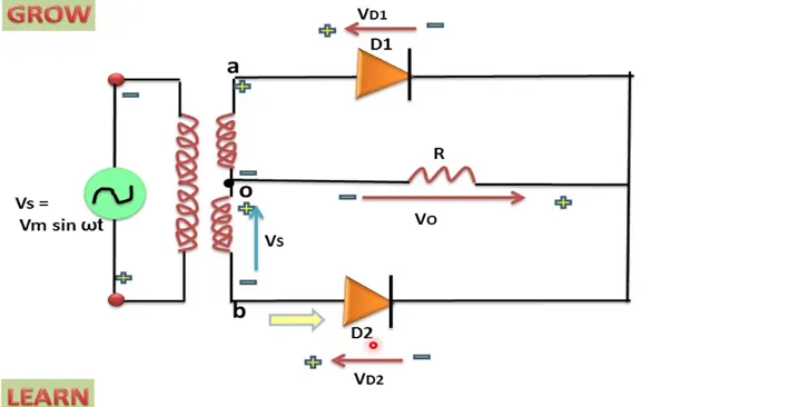
This converter rectifies both +ve and -ve half-cycles of the input supply. It uses two diodes with center-tapped secondary transformer as shown in the figure. In +ve half-cycle of the input supply, diode D1 is forward biased while D2 is reverse biased. When D1 is triggered, the supply voltage appear across the load.
It conducts till 180 degree if input supply and turns OFF due to natural commutation. During -ve half-cycle, thyristor D2 is forward biased and when it is triggered, it starts conducting. It conducts till next +ve half-cycle gets triggered.The load could be RL or Rfe depending on the type of application it is employed. This type of converter produces an output voltage twice that of single phase half-wave rectifier. These are essential when one of the terminals on DC side has to be grounded. However, a center-tapped transformer with a VA rating double that of load is required and also high voltage rating thyristors are needed in this converter.
c. Single Phase Full-Wave Bridge Rectifier:
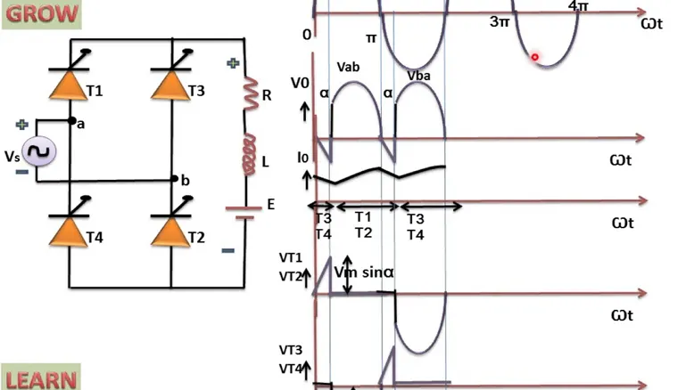
This is the circuit diagram of a full wave bridge rectifier using thyristors as shown in the figure below. It consists of 4 SCRs which are connected between single phase AC supply and a load.
This rectifier produces controlled DC by varying conduction of all SCRs. In +ve half- cycle of the input, thyristors T1 and T2 are forward biased while T3 and T4 are reversed biased. Thyristors T1 and T2 are triggered simultaneously at the same firing angle in that positive half-cycle, T3 ad T4 are triggered in the -ve half cycle.
The load current starts flowing through them when they are in conduction state. The load for this converter can be RL or Rfe depending on the application. By varying the conduction of each thyristors in the bridge, the average output of this converter gets controlled. The average value of the output voltage is double that of half-wave rectifier.
d. Three-Phase Full-Wave Controlled Converter:
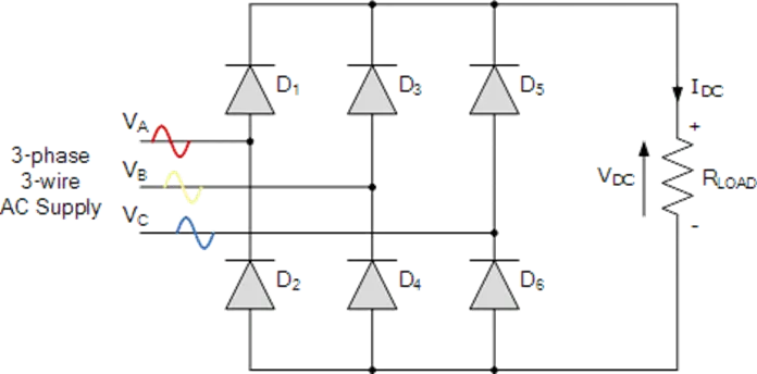
It is obtained by connecting to DC terminal of two 3 pulse converter in series. It is also called 6-pulse converter. This type of converter is used in industrial applications where 2 quadrant operation is required. Here the load is connected via a 3 phase half wave connection to one of three suplly lines. Thus, there is no need of transformer, however, for isolation purpose a 3-phase AC supply is provided from transformer is connected as shown in figure.
Here thyristors D1,D3 and D5 forms a +ve group, whereas thyristors D4, D6 and D2 forms a -ve group. This +ve group of diodes are turned ON for +ve supply voltage and -ve group diodes are turned ON for -ve supply voltages. In this, one of the diode from +ve, whose anode voltage is maximum, +ve will conduct at any instant and simultaneously one of the diode from -ve group, whose cathode voltage is maximum, -ve will conduct.
This converter can be connected to RL or Rfe loads. By controlling the firing angle to respective thristor, average power delivered to the load is changed. The firing angle of particular thyristor in +ve group measured from the instant when its anode becomes maximum +ve. Similarly, the firing angle for a thyristor in negative group is measured from the instant when its cathode terminal attains a maximum -ve value.
2. DC to DC Converter:
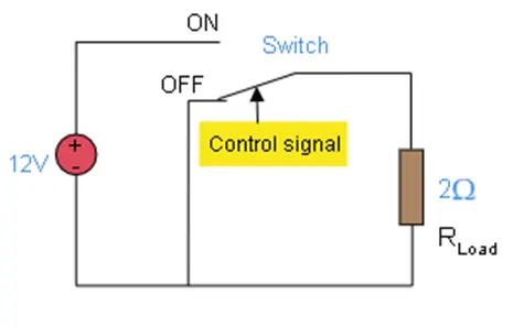
Many DC operated applications need different levels of DC voltage from a fixed DC source. Some of these applications include subway cars, Dc traction systems, control of large DC motors, battery operated vehicles, trolley buses etc. they require variable DC to produce variable speed, so a power conversion device is needed.
A DC chopper is a static device that converts a fixed input DC voltage to variable DC output or a fixed DC output of different magnitude (which can be lower or higher) than input value. The block diagram of a DC chopper is shown in figure below:
The chopper circuit is connected between DC input source and DC load. This chopper consists of power electronics switching devices such as thyristors which are connected in such a way that they produce required DC voltage to the load. The output voltage is controlled by adjusting ON time of the thyristor (or switch) which turn changes the width of DC voltage pulse at the output. This method of switching is called as pulse width modulation (PWM) control.
The output of the chopper can be less or greater than the input and also it can be fixed or variable. These can be unidirectional or bi-directional devices based on the application it is intended for. DC chopper are mainly used in DC drives, i.e, EVs and HEVs. DC chopper are classified into 3 basic types based on input and output voltage levels and are discussed below:
I. Step-Down Chopper or Buck Converter:
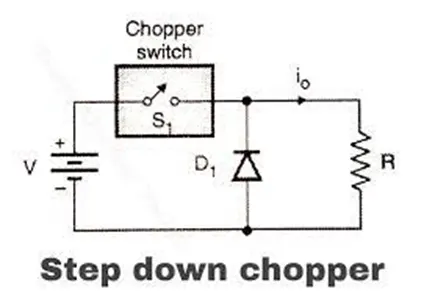
A step-down chopper produces an average output voltage lower than the input DC voltage. The circuit for this converter is shown in figure below. Here the switching component is thyristor that switches the input voltage to the load when it is triggered at particular instants.
A diode acts as a free wheeling diode that allows the load current to flow through it when thyristor is turned OFF. If this diode is absent, a high induced EMF in inductance may cause damage to the switching device.
The average output voltage of the converter is varied by controlling turn ON/OFF periods of thyristor. When thyristor is turned ON, the output voltage is same as the input voltage and if it is turned OFF, the output voltage equals to zero(0).
Output Voltage = Total time interval during(ON)/ Total time interval(T)
So, Duty Cycle = Ton/T, the output voltage will be increased.
II. Step-Up Chopper or Boost Converter:
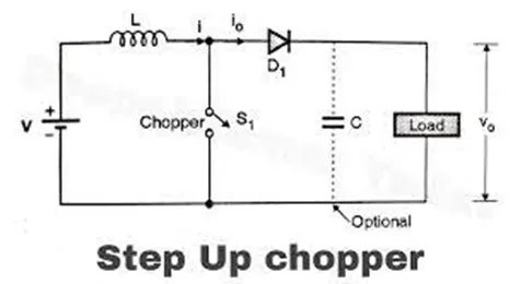
In this chopper, the output voltage is always greater than input voltage. The configuration of a boost converter is shown in figure below. Here, also a switch is used, which is connected in parallel with the load. This switch is a thyristor or an SCR. As similar to the buck converter, a diode is placed in series with the load that allows the load current to flow when the thyristor is turned OFF.
When the thyristor is turned ON, the diode is reverse -biased and hence it isolates the load circuit from the source. So the inductor charges to the maximum input voltage source. When the thyristor is turned OFF, the load gets the voltage from input as well as from inductor. So the voltage appearing across the converter output will be more than the input. Here, the output voltage is equal to (1/1-d) times the input voltage, where d is the duty ratio (TON/T). By varying this duty ratio, the output voltage will be varied till the load gets desired voltage.
III. Buck/Boost Converter:
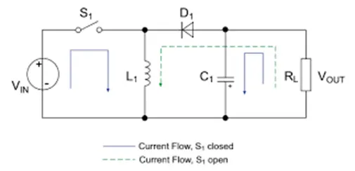
This chopper can be used both in step-down and step-up modes by continuously adjusting its duty cycle. The configuration of buck-boost converter is shown in figure below that consists of only one switching device, i.e one thyristor.
Along with an inductor and diode, additional capacitor is connected in parallel with this circuit. When the thyristor is turned ON, the supply current flows to the inductor through the thyristor and induces the voltage in inductor.
When the thyristor is turned OFF, the current in the inductor tends to decrease with the induced EMF reversing polarity. The output voltage of this converter remains constant as capacitor is connected across the load.
By varying the value of duty ratio to a certain value, the output voltage is lower than the input voltage, typically in the range
3. DC to AC Converter or Inverter:
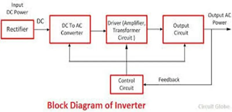
These Converter are connected between DC source of fixed input, and variable AC load. Most commonly these DC to AC converters are called as inverters. An inverter is a static device that converts fixed DC supply voltage to variable AC voltage.
Here the fixed DC voltage is obtained from batteries or DC link in most power electronic converter. The output of the inverter can be variable/ fixed AC voltage with variable/ fixed frequency.
This conversation from DC to AC along with variable suppy is produced by varying the triggering angle to the thyristors. Most of the thyristors used in inverters are employed with forced commutation technique.
These can be single phase or three phase inverter depending on the supply voltage. These converters are mainly divided into two groups. One is PWM based inverters and other multilevel inverters.
Further, these are classified voltage source inverter and current source inverter. Each type is subdivided into different types such as PWM, SVPWM etc. multilevel inverters are more popular in industrial applications. The inverters overcome the drawbacks of PWM based inverters.
4. AC to AC Converter:
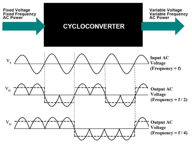
AC to AC converters is used for converting the AC waveforms with one particular frequency and magnitude to AC waveform with another frequency at another magnitude. This conversion is mainly required in case of speed controlling of machines, for low frequency and variable voltage magnitude applications as well. We know that there are different types of loads that work with different types of power supplies like single-phase, three-phase supply, and the supplies can be differentiated based on the voltage and frequency range also. The AC to AC converters can be classified into different types:
- Cyclo-Converters
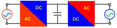
- AC to AC Converters with DC link
- Matrix Converters
- Hybrid Matrix Converters
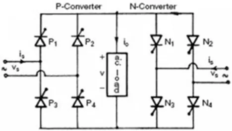
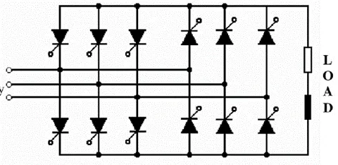
1-Ø to 1- Ø Cyclo-converter 3-Ø to 1- Ø Cyclo-converter
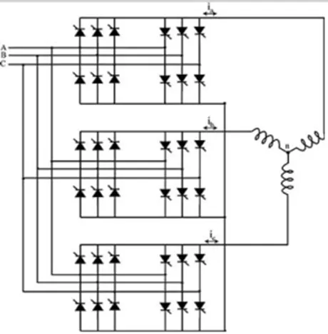
3-Ø to 3- Ø Phase Cyclo-converter Phase controlled Cyclo-converters
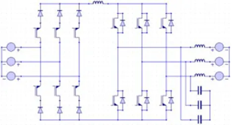
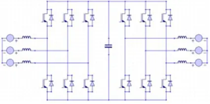
Current Source Inverter Converter Voltage Source Inverter Converter
2. An Electric Vehicle's powertrain with 72V battery pack in shown in the diagram below. The duty ratio for acceleration operation is 'd1' and for the braking operation the duty ratio is 'd2'.
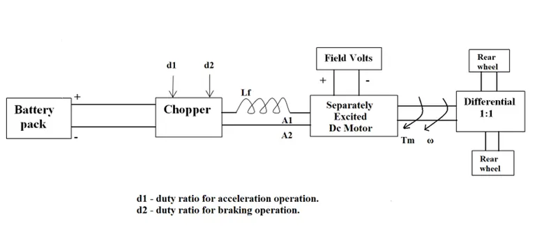
The other parameters of the electric vehicle is given below,
Motor and Controller Parameters:
Rated Armature voltage= 72 V
Rated armature current= 400 A
Ra= 0.5Ω, KΦ= 0.7 Volt second
Chopper Switching frequency= 400 Hz
The vehicle speed-torque characteristics are given by the below equation.

What is EV steady state speed if duty cycle is 70% ?
Ans:
The following input parameters are given below:
- Battery Voltage (Va) = 72 V
- Rated Armature Current = 400 A
- Armature Resistance (Ra) = 0.5 ohm
- Motor Constant (Kϕ) = 0.7 V-s
- Chopper Frequency (F) = 400 Hz
- Duty Cycle = 70 % = 0.7
Mathematical Solution:
Vehicle Output voltage (Vo) = Va × Duty Cycle
= 72 × 0.7
= 50.4 V
Now, the equation of the vehicle torque is given by :
Tm = (Vo*Kϕ)/Ra – (Kϕ)^2/Ra*N …………………… (1)
Where N = Speed of the motor in radian/sec or radian/min.
Tm = Motor Torque in N-m
Vo = Vehicle Output Voltage in Volt.
Kϕ = Motor Constant in Volt-sec.
Ra = Armature Resistance in ohm.
Now, substituting the given data of the parameter in the equation (1), we get
Tm = (50.4 × 0.7)/0.5 – (0.7)^2/0.5 × N
Tm = 70.56 – 0.98 × N …………………………… (2)
Now, the vehicle speed-torque characteristics is given as,
Tv = 24.7 + 0.0051 × N^2 …………………………… (3)
At steady state,
Eqn (2) = Eqn (3) where Tm = Tv, then
70.56 – 0.98 × N = 24.7 + 0.0051 × N^2
0.0051N^2 + 0.98N - 45.86 = 0 …………………… (4)
To solve the above equation (4) with quadratic equation formula, we get
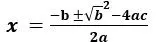 ………………………… (5)
Now, put the value from eqn. (4) to eqn. (5)

On solving this equation we get the final steady state value of vehicle speed which is 38.92 rad/sec.
For RPM value:
N(rpm) = N × 
= 38.92 ×
=  = 371.85 RPM
So, the steady state value of the vehicle speen for the given data is 38.92 rad/sec or 371.85 rad/min.
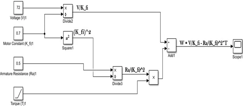
3. Develop a mathematical model of a DC Motor for the below equation using Simulink.
ω= (V/Kϕ) –(Ra/Kϕ^2 ).T
Ans : Let us draw a model for the above equation.
Let Va = 72 Volts.
Kϕ= 0.7
Ra = 0.5
and also let consider torque as a linearly increasing signal.
Model:
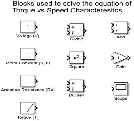
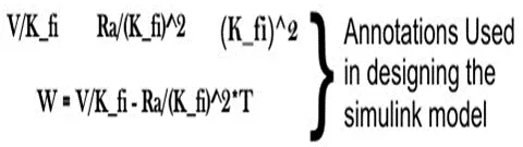
Finally model is ready to run using the blocks as mentioned above and I got the graphical representation of the given equation through using scope block.
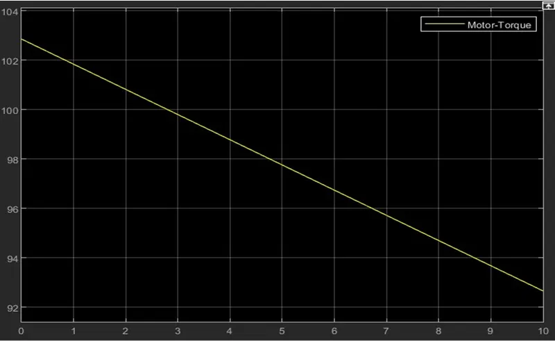
4. Refer to the blog on below topic: Induction Vs DC brushless motors by Wally Rippel, Tesla. Explain in brief about author’s perspective.
Ans: This blog is about the Walley Rippel perspective about brushless DC and induction motor. Walley is a long-time proponent of Electric Vehicle. He was engineer at AeroVironment, where he was helped to develop the EV1 for general motor. He also worked in jet propulsion laboratory on electric vehicle battery research, among other projects.
"Proponent means someone who is in favour of something."
In the starting of the blog he said that “One size doesn’t fit all”. He said, In this odious world when engineers are of the different type and of different domain. He said one would think that year ago, some was trying to figure out which is best engine and that should be in production but his thought got failed. There is no one is best one with the different requirements there are different type of engine such a way that he said this is true for BLDC and Induction Motor. He also said about the evolution of batteries DC brush motor contactor and controllers.
He said the lead acid battery is replaced by the Li battery and brush DC motor with BLDC or Induction Motor. Next, he gives some closer look of the BLDC and Induction Motor about technologies and about its working.
He also speaks about the things that what differentiate them? In that he told about BLDC machine that rotor generate the magnetic field with two or more permanent magnet and this magnetic field enters the stator core (a core made up of thin, stacked laminations) and interacts with currents flowing within the winding to produce a torque interaction between the rotor and stator. As the result of rotor rotates, it is necessary that the magnitude and polarity of the stator currents be continuously varied – and in just the right way – such that the torque remains constant and the conversion of electrical to mechanical energy is optimally efficient. The device that provides this current control is called an inverter. He also told one important thing that without an inverter, BLDC are useless motors.
Then he explains about induction motor drives. He curiously told that stator of the both BLDC and induction motor have three sets of “distributed windings” the only difference is in the rotor of induction motor that currents flowing in the stator windings produce a rotating magnetic field that enters the stator windings produce a rotating magnetic field that enters the rotor. In turn, the frequency of this magnetic field as “seen” by the rotor is equal to the difference between the applied electrical frequency and the rotational “frequency” of the rotor itself.
Accordingly, an induced voltage exists across the shorted structure that is proportionate to this speed difference between the rotor and electrical frequency. In response to this voltage, currents are produced within the rotor conductors that are approximately proportionate to the voltage, hence the speed differ. Finally, these currents interact with the original magnetic field to produce forces in a component of which is the desired rotor torque.
He said that induction motor not require inverter and the motor has ability to start under the load. With the fixed utility power BLDC produces no starting torque it needs an inverter. Induction motor not operate under the DC source. Next, he is talking about the heading “Brushless or Induction”. He told that back 1990s all EV except one uses the BLDC drives and today all HEV using the BLDC. Then he gave some comparison between DC brushless and induction motor.
|
|
BLDC |
Induction Motor |
|
1. |
Require an absolute position sensor. |
Require an absolute position sensor. |
|
2. |
Power factor is unity. Less rotor heat is generated, rotor cooling is easier and peak point efficiency higher. |
Power factor is about 85%. Peak poit efficiency is higher compare to BLDC. |
|
3. |
Strength of magnetic field produced by the permanent magnet would be adjustable. To get max. torque the magnetic field should max. at low speed maintained by the inverter and motor current low. |
No magnet and magnetic fields are adjustable, since magnetic field is proportionate to V/f. Efficiency is maximized due to low magnetic losses. |
|
4. |
Average efficiency is low. |
Average efficiency is high. |
|
5. |
Permanent magnet are expensive. |
No magnet is there which is the advantage in cost. |
|
6. |
They are easy to control. |
The controls are more complex and difficult to understand, so difficult to control as well too. |
By differentiating both BLDC and Induction Motor still No winner is decided as he describes that no one is best neither BLDC motor nor Induction Motor. The author couldn’t choose which drive is better than other but makes it clear that BLDC motor drives likely continue to dominate in the HEV and upcoming Plug-in HEV market while induction motor drives likely to maintain the dominance for the high-performance of pure EV. Finally, he concluded that both are best suited as per the requirements.