Week -2
Simulink for ELECTRICAL and MECHANICAL Engineer
Challenge – 2
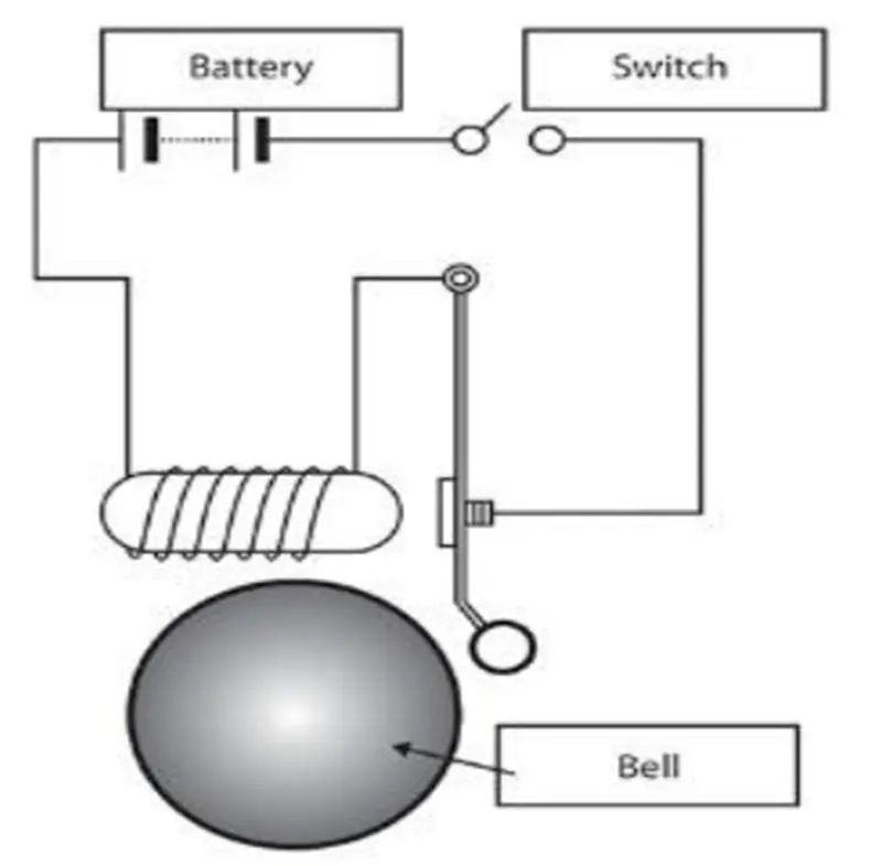
Q 1. Make a Simulink model of Doorbell using solenoid block with the following details:
In the above arrangement, when the switch is closed the electromagnet receives electrical power from the battery and pulls the metal arm to hit the bell producing sound.
Create a situation where the switch is closed for 2 seconds and then released. Observe the physical movement of the plunger.
Assume remaining parameters.
Answer :
Objective:
Make a Simulink model of Doorbell using solenoid block.
Theory :
Linear Solenoid
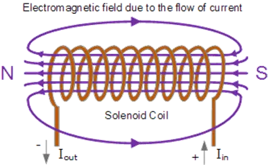
Linear solenoid is basically consist of an electrical coil round around a cylindrical tube with a ferro-magnetic actuator or “plunger” that is free to move or slide “IN” and “OUT” of the coils body. Solenoids can be used to electrically open doors and latches, open or close valves, move and operate robotic limbs and mechanisms, and even actuate electrical switches just by energising its coil.
Linear Solenoid
When an electrical current is passed through the coils windings, it behaves like an electromagnet and the plunger, which is located inside the coil, is attracted towards the centre of the coil by the magnetic flux setup within the coils body, which in turn compresses a small spring attached to one end of the plunger. The force and speed of the plungers movement is determined by the strength of the magnetic flux generated within the coil.
When the supply current is turned “OFF” (de-energised) the electromagnetic field generated previously by the coil collapses and the energy stored in the compressed spring forces the plunger back out to its original rest position. This back and forth movement of the plunger is known as the solenoids “Stroke”, in other words the maximum distance the plunger can travel in either an “IN” or an “OUT” direction.
Linear Solenoid Construction
This type of solenoid is commonly called a Linear Solenoid due to the linear directional movement and action of the plunger. Linear solenoids are available in two basic configurations called a “Pull-type” as it pulls the connected load towards itself when energised, and the “Push-type” that act in the opposite direction pushing it away from itself when energised. Both push and pull types are generally constructed the same with the difference being in the location of the return spring and design of the plunger.
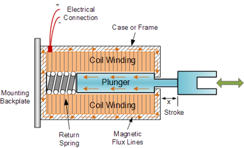
Pull - Push-type Linear Solenoid Construction
Linear solenoids are useful in many applications that require an open or closed (in or out) type motion such as electronically activated door locks, pneumatic or hydraulic control valves, robotics, automotive engine management, irrigation valves to water the garden and even the “Ding-Dong” door bell has one.
Observation :
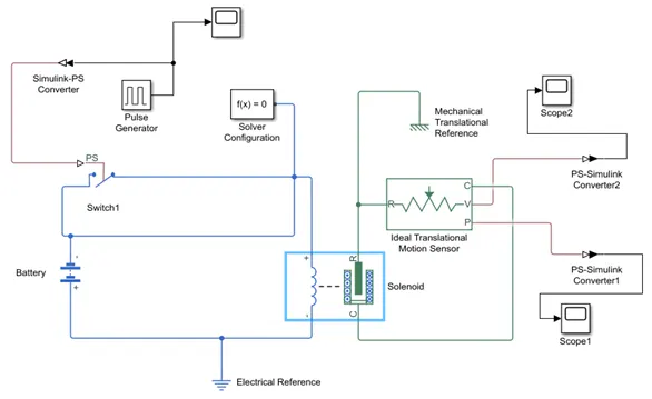
Simulink Model Explanation
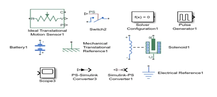
Pulse Generator :The pulse generator is used to create square wave pulses at regular intervals. The block waveform parameters Amplitude, Pulses Width period and phase delay determine the shape of the output waveform.
Switch :The switch block used is controlled by external physical signal. If the external signal is greater than the threshold parameter then the switch is closed, otherwise switch is open.
Battery : The positive terminal of the switch is connected to switch and the negative terminal is connected to the electrical reference.
Solenoid : The solenoid block is connected with switch and battery and we will get a complete electrical circuit. The port C is connected with mechanical reference.
Ideal Translational Motion Sensor : The ideal translational sensor is connected with solenoid block R to observe the movement of the plunger.
Scope : Scope is connected with the ideal translational sensor to get the output.
PS-Simulink converter : is used to convert the physical signal to Simulink signal.
Simulink-PS Converter : It is used to convert Simulink signal into physical signal.
Solver Configuration : Each physical network represented by a connected simscape blocks requires solver settings information for simulation.
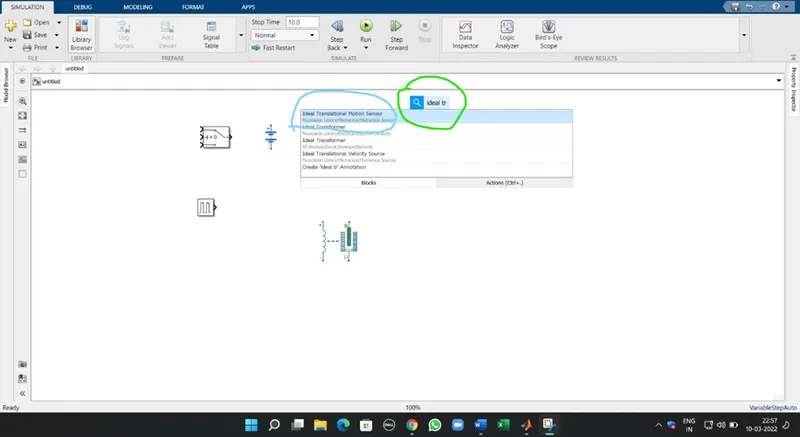
This is how I search all the blocks in Simulink which is on my finger tip. Just by right click anywhere and write the name of the block and get a number of result by Simulink library.
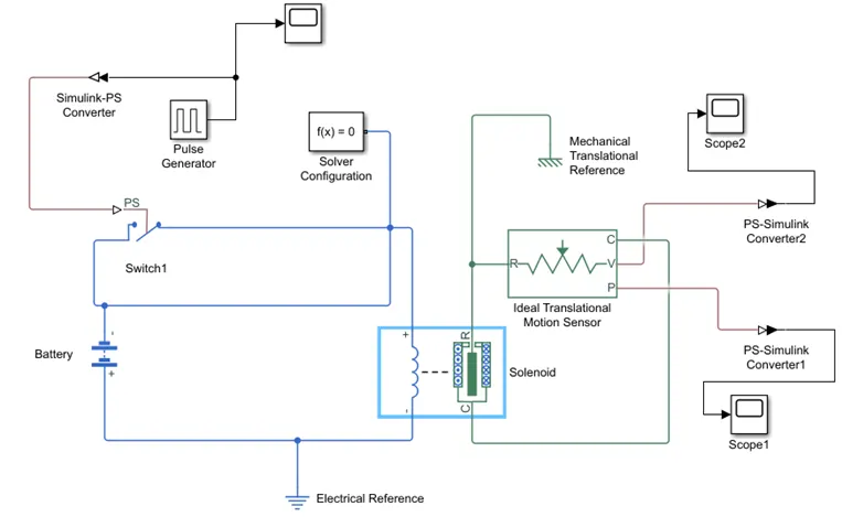
This is the circuit diagram / Simulink model of Door bell using solenoid block, battery, pulse generator, switch, ideal translational motion sensor, PS-Simulink & Simulink-PS converter, Electrical & mechanical reference and finally scope is used to get the result in the form of signal .
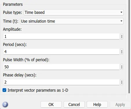
This is some parameters like amplitude, pulse width, phase delay and time period which is adjusted and changed according to condition given in the question i.e. when the switch is closed the electromagnet receives electrical power from the battery and pulls the metal arm to hit the bell to produce sound.
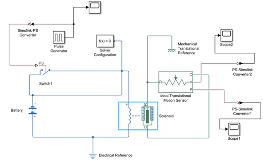
Simulink Model when plunger R is away from C
Simulink Model when plunger R is towards C.
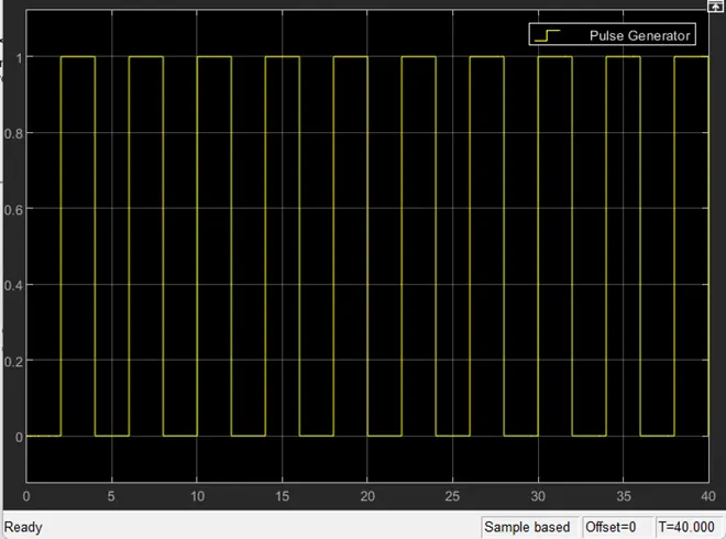
This is the graph plotted as shown above is the time period of pulse generator which acts for 4 sec period of time with 2 sec phase delay & the pulse width is 50 which is unchanged and it runs with stop time 40 sec.
Conclusion :
Time period given is 2 sec to the PG to open & close the switch. When the switch is closed the solenoid receives the electrical power from the battery and the plunger move from R to C and hit the bell and sound is produced. Physical movement of the plunger is observed by using translational motion sensor & physical output is converted into Simulink output model is displayed in the scope.
Q 2. Use a thermistor to sense the temperature of a heater & turn ON or OFF the fans as per the below conditions :
Given Conditions :
- Temperature source : 20ºC from 0 to 10 seconds, 27ºC from 10 to 30 seconds, 23ºC from 30 to 50 seconds.
- Fan Conditions : ON if the temperature above 25ºC , OFF otherwise.
Answer :
Objective :
To sense the temperature of a heater & turn ON or turn OFF the fan using Thermistor as per the following conditions:
Condition 1 : Temperature source : 20ºC from 0 to 10 seconds, 27ºC from 10 to 30 seconds, 23ºC from 30 to 50 seconds.
Condition 2 : Fan should be ON if the temperature above 25ºC & should be OFF otherwise.
Theory :
Thermistor :
Thermistor is a device which measures the temperature, its working is based on the relationship between resistance and temperature. Here in Simulink the thermistor block which is available is a positive temperature co-efficient thermistor. So here resistance of thermistor increases or decreases with respect to temperature, the output from the thermistor is actually in the form of voltage or current. The increase in voltage / current indicates increase in temperature.
Simulink model Explanation
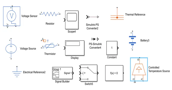
Controlled Temperature Source : It represents an ideal source of thermal energy, that can maintain a controlled temperature difference across source regardless of the heat flow rate.
The temperature difference is set by the physical signal port S. A positive temperature difference causes the temperature at port B to be greater than the temperature at port A.
Thermistor : It is a type of resistor whose resistance is based upon temperature.
Resistor : A linear resistor is used inorder to control the amount of current from the battery.
The Voltage Sensor : It is used to convert the voltage measured between two points of electrical circuits into a physical signal.
Voltage Source : It implement the voltage source which represent DC or AC source & noise components.
Electrical Reference : This block is used here to help the electrical block system given.
Solver Configuration : Each physical network represented is connected with simscape blocks requires solver setting information for simulation.
Calculation & Observation :
Simulink Building block is used to input the values as per given conditions :
- At point 1, Time = 0 seconds, Temperature = 293 K
- At point 2, Time = 10 seconds, Temperature = 293 K
- At point 3, Time = 10 seconds, Temperature = 300 K
- At point 4, Time = 30 seconds, Temperature = 300 K
- At point 5, Time = 30 seconds, Temperature = 296 K
- At point 6, Time = 50 seconds, Temperature = 296 K
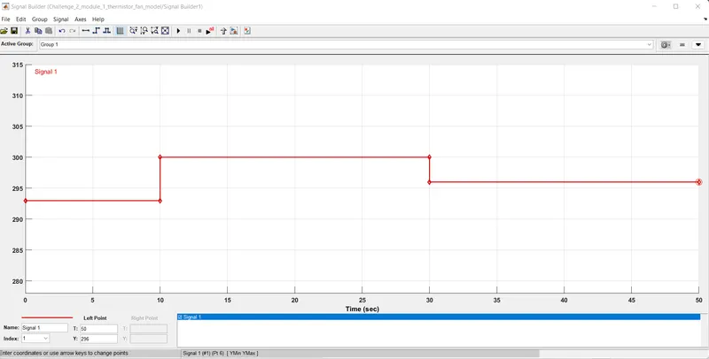
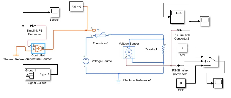
There is parameters which to be changed to check the fan ON & OFF condition at some given temperature with rest to time given in signal builder block above (in the plot graph).
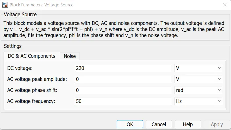
Here, I changed the value of dc voltage source from 25 to 220 V and left others keep uncahnged.
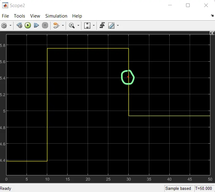
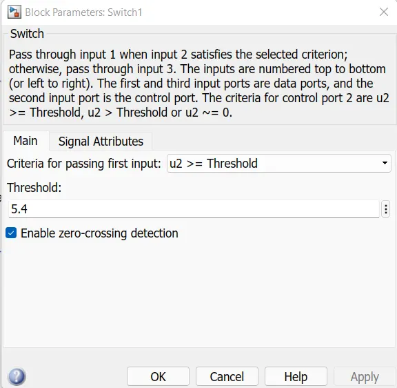
With the help of scope used to connect with voltage sensor and PS - Simulink converter give the threshold value and then I put the value of threshold voltage in the switch to get the final output through scope.
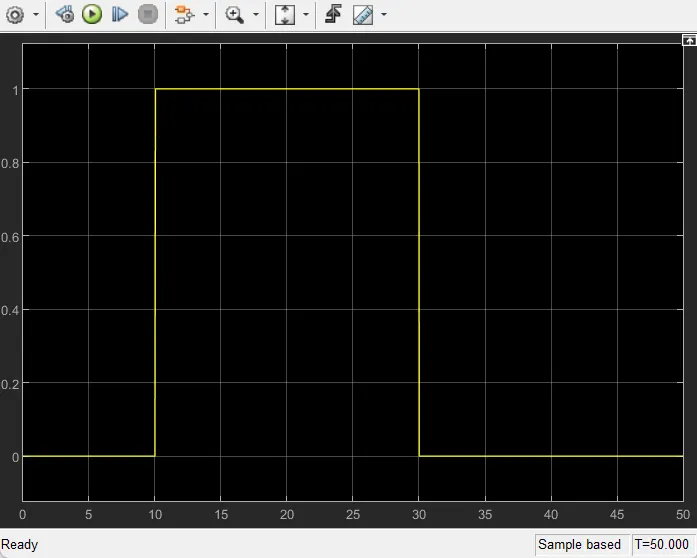
After running the model for stop time 50 sec (as I have mentioned above in the condition), the final output which i got from scope connected with the switch along with On & Off constant and the plot give the correct information that model run particualrly in the same condition as given to it.
Conclusion :
For 0 to 10 sec fan is OFF condition because temperature is 293k which is below the threshold 298K. After 10 sec temperature goes to 300K then the switch will be in ON condition as the temperature comes down to 296K which is below the threshold temperature of 298K. All above conditions are evaluated and can be plotted in the graph.