Week - 4
AIM :
- To Implement control logic of a “washing machine” using Stateflow as per given sequence.
- To Make a Simulink chart for the “Gear shift” logic as per given conditions.
OBJECTIVE
- To implement control logic of a washing machine using Stateflow as per given sequence: -
- If the power supply is available, the system gets activated
- If the water supply is not available, stop the process and indicate through LED
- Soaking time should be 200s followed by Washing time of 100s
- Then rinsing happens for next 20s and dryer runs for 50s
- After all the processes have completed turn on the finished LED
- Make a Simulink chart for the gear shift logic as per below conditions:
Speed Range(kmph) Gear
0 to 15 1
16 to 25 2
26 to 40 3
41 to 60 4
Above 61 5
EXPLANATION FOR CONTROL LOGIC OF A WASHING MACHINE USING STATE FLOW:
State Flow is a Simulink tool to implement the state machine.
Here model system logic of a Washing Machine using State flow has been done.
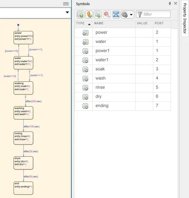
Create a chart and enter the given input conditions.
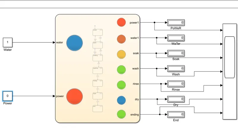
Step 1 : Given Input Conditions : If the power supply is available, the system gets activated
If the Water supply is not available, stop the process & indicate through LED Soaking time should be 200s followed by Washing time of 100s.
Then rinsing happens for next 20s & dryer runs for 50s
Step 2 : After entering the input conditions in the chart, Go to Symbols pane and assign the given variable. (Example : input data, Output data,etc..)
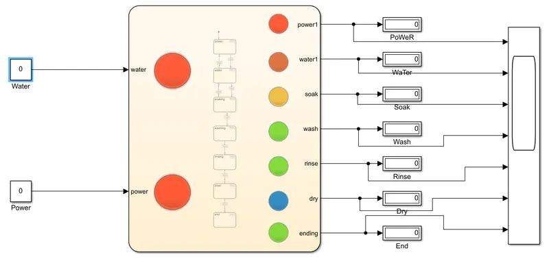
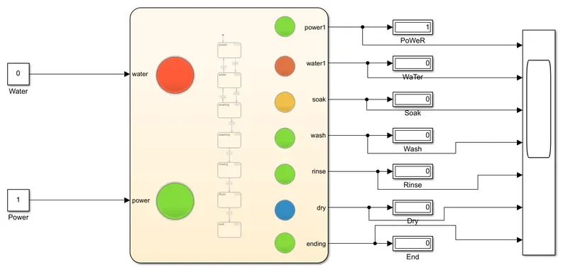
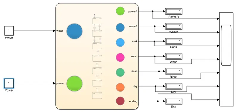
Step 3 : Give the input values for turning on or off for the Power Supply and Water Supply.
Condition : if value =1, Power and water Supply will turn On.
if value = 0, Power and water Supply will turn off.
Step 4 : Use 'display' block and 'Lamp' indicator to display the results.
Input #1:
Power: OFF, Water: OFF
Input #2:
Power: ON, Water: OFF
Input #3:
Power: ON, Water: ON
Input #4:
Power: OFF, Water: ON
GEAR SHIFTING MECHANISM :
Mechanical devices that enable the driver to engage gears in such a way as to obtain the desired transmission ratio are called shifting mechanisms.
EXPLANATION FOR GEAR SHIFTING MECHANISM USING SIMULINK:
Step 1 : Create a chart and enter the given conditions for gear shifiting. Given Conditions :
Speed Range(kmph) Gear
0 to 15 1
16 to 25 2
26 to 40 3
41 to 60 4
Above 61 5

Step 2 : After entering the input conditions in the chart, Go to Symbols pane and assign the given variable. (Example : input data, Output data,etc..)
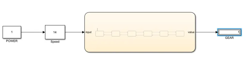
Step 3 : Connect the 'Slider Gain' to vary the speed while simulation is running.
Step 4 : Create Constant and giving value 1 and o for turning on & off.
Step 5 : Use 'display' Block to display the Gear position.
Case - 1: For 14 kmph, the gear shifts from Neutral to 1st gear as per the condition.
Case - 2: For 42 kmph, the gear shifts from 1st gear to 2nd gear as per the condition.

Case - 3: For 38 kmph, the gear shifts from 2nd gear to 3rd gear as per the condition.

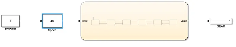
Case - 4: For 48 kmph, the gear shifts from 3rd gear to 4th gear as per the condition
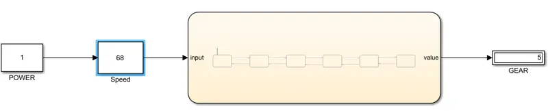
Case - 5: For 68 kmph, the gear shifts from 4th gear to 5th gear as per the condition
CONCLUSION:
- The washing machine works according to the input supply of power & water else it won't work and indicated by lamp light green and red respectively.
- As the speed varies the gear shift done by automatically as per the given condition and the change of gear indicated by lamp light as the speed varies from 0 - 70 kmph.