Week -2
AIM:
- To Make a Simulink model of Doorbell using solenoid block.
- To use a thermistor to sense the temperature of a heater & turn on or turn off the fan
OBJECTIVE:
- To Create a situation where the switch is closed for 2 seconds and then released. Observe the physical movement of the plunger.
- To sense the temperature of a heater by using some condition are given below Temperature source: 20 °C from 0 to 10 seconds, 27 °C from 10 to 30 seconds, 23 °C from 30 to 50 seconds Fan conditions: ON if the temperature above 25 °C, OFF
THEORY:
Door Bell When you press a doorbell button, you complete an electrical circuit that allows household electricity to flow through the doorbell's internal electromagnet. The magnetic field generated by the electromagnet is then used to power a mechanism that creates the doorbell sound. Doorbells are low voltage devices
Solenoid is the generic term for a coil of wire used as an electromagnet. It also refers to any device that converts electrical energy to mechanical energy using a solenoid. The device creates a magnetic field from electric current and uses the magnetic field to create linear motion, and hence it causes the hammer to strike the gong at regular intervals.
Blocks Used:-
Pulse Generator:- The Pulse Generator block generates square wave pulses at regular intervals. The block waveform parameters, Amplitude, Pulse Width, Period, and Phase delay, determine the shape of the output waveform.
Simulink-PS Convertor:- Converts the Simulink input signal to a Physical Signal.
Switch:- The block represents a switch controlled by an external physical signal. If the external physical signal PS is greater than the threshold, then the switch is closed, otherwise the switch is open
Battery :- It provides voltage to the system
Solenoid Block:- Shows the position of the plunger with respect to the EMF induced, which depends on the initial position of the plunger. The spring constant is set to zero
Mechanical & electrical reference :- these provides the reference point to the respective signals
Ideal Translational Motion Sensor :- The block represents an ideal mechanical translational motion sensor, that is, a device that converts an across variable measured between two mechanical translational nodes into a control signal proportional to velocity and position.
Scope :- to view the characteristics of a property with respect to the time(Simulation Time)
Solver Configuration: Each physical network represented by a connected Simscape block diagram requires solver settings information for simulation. The Solver Configuration block specifies the solver parameters that your model needs before you can begin simulation.
Simulink Model For Doorbell
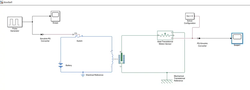
Simulink Model Explanation:
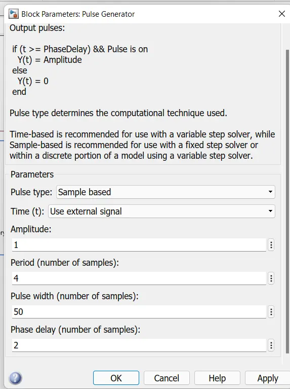
- The pulse generator is used to create square wave pulses at regular intervals. The block waveform parameters Amplitude, pulse width, period and phase delay, determine the shape of the output waveform.
- The switch block used is controlled by external physical signal. If the external signal is greater than the threshold parameter then the switch is closed, otherwise switch is open.
- The positive terminal of the switch is connected to switch and the negative terminal is connected to the electrical reference.
- The Solenoid block is connected with switch and battery and we will get a complete electrical circuit. The port c is connected with mechanical reference.
- The ideal translational sensor is connected with solenoid block R to observe the movement of the plunger.
- Scope is connected with the ideal translational sensor to get the output.
- PS-Simulink converter is used to convert the physical signal to simulink signal.
- Solver Configuration: Each physical network represented by a connected simscape blocks requires solver setting information for simulation
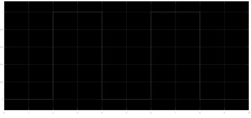
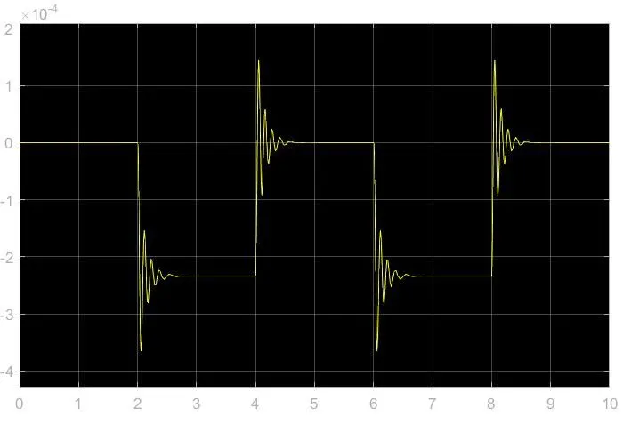
- The above figure is obtained by running the Simulink Model and double clicking the “Scope1 Block”. This figure shows how the Pulse is generated and in this figure the X-axis represents the “Time” and Y-axis represents the “Amplitude”. As mentioned in the point no.18, the Pulse has started from 2 sec and ending at 6 sec which is nothing but a time period of 2 secs.
- Now Run the Model and Double click on the “Scope2 Block” which is connected to “Ideal Translation Motion Sensor Block” to get the results.
- Thus, this represents that when amplitude is 1, the switch will be close and current will start flowing and when it is zero the switch will open and current stop flowing. Since our objective is only to see the change in position of Plunger when Switch is Close for 2 sec , so we have the Amplitude as 1 for 2 sec in the Pulse generator by making the Pulse width half of the period in the inputs fir “Pulse Generator Block”.
- Since the Pulse that is coming from “Pulse Generator Block” is a Simulink value, so to convert this value into Physical value we have used “Simulink-PS Converter Block”, since Switch only takes Physical value as Inputs.
- As mention above, the port “P” of “Ideal Translation Motion Sensor Block” is connected to another “Scope2 Block” and a “Solver Configuration Block” is also connected to this path which generates Equations and solves the whole Model internally to give the results of the Whole Simulink Model output.
- Now Run the Model and Double click on the “Scope2 Block” which is connected to “Ideal Translation Motion Sensor Block” to get the results.
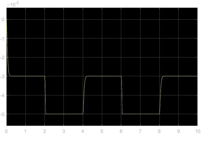
- We will get the above Graph as the result when we double click on “Scope2 Block”. Here X-axis Represent the “Time” and the Y-axis represent position of Plunger in mm.
- From the above figure we can observe that the initial position of the Plunger is at “5mm” as from Pulse generator Block, a Pulse generated at 2, so in the position of the Plunger is also changing at time 2 seconds and time till which the Pulse Amplitude is “1” till that time plunger is also at the same position after the change from initial position.
THERMISTOR:
A thermistor is a resistance thermometer, or a resistor whose resistance is dependent on temperature. The term is a combination of “thermal” and “resistor”. It is made of metallic oxides, pressed into a bead, disk, or cylindrical shape and then encapsulated with an impermeable material such as epoxy or glass.
Thermistors are easy to use, inexpensive, sturdy, and respond predictably to changes in temperature. While they do not work well with excessively hot or cold temperatures, they are the sensor of choice for applications that measure temperature at a desired base point. They are ideal when very precise temperatures are required.
Temperature Range: The approximate overall range of temperatures in which a sensor type can be used. Within a given temperature range, some sensors work better than others.
Given Inputs:
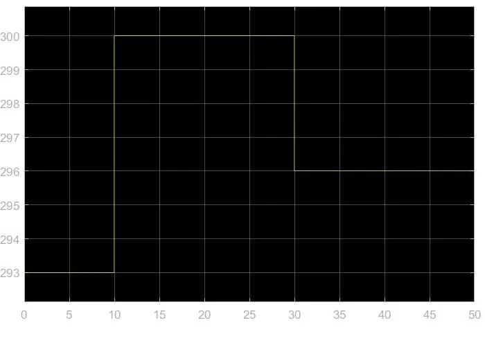
Temperature source: 20 °C from 0 to 10 seconds, 27 °C from 10 to 30 seconds, 23 °C from 30 to 50 seconds
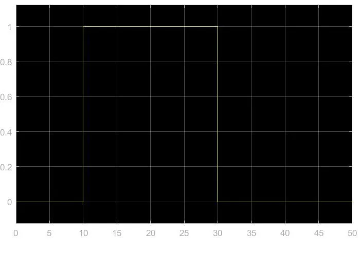
Fan conditions: ON if the temperature above 25 °C, OFF otherwise
Simulink Mode of thermistor
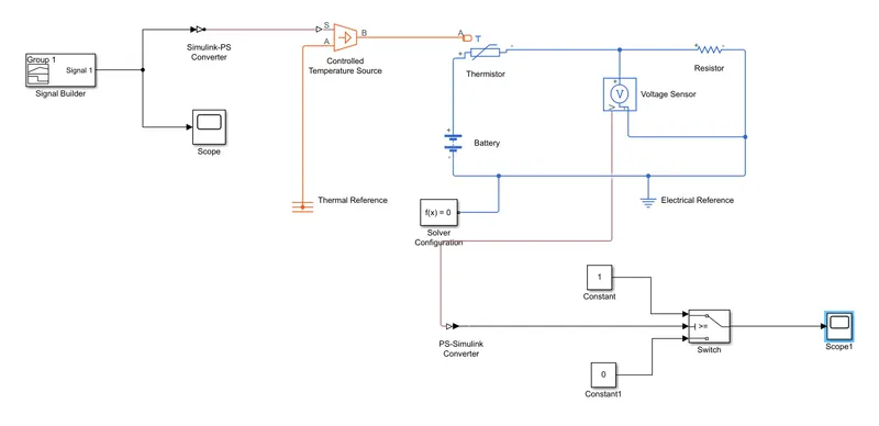
Simulink Model Explanation:
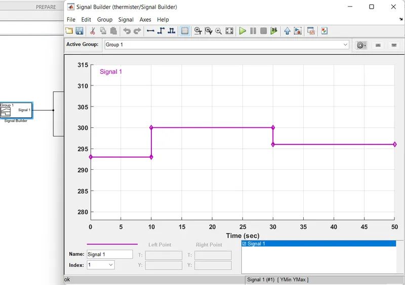
Signal Builder block is used to input the values as per given conditions
At point 1,Time=0 seconds, Temperature=293 K
At point 2,Time=10 seconds, Temperature=293 K
At point 3,Time=10 seconds, Temperature=300 K
At point 4,Time=30 seconds, Temperature=300 K
At point 5,Time=30 seconds, Temperature=296 K
At point 6,Time=50 seconds, Temperature=296 K
- Controlled Temperature source represents an ideal source of thermal energy, that can maintain a controlled temperature difference regardless of the heat flow rate.
- The temperature difference is set by the physical signal port S. A positive temperature difference causes the temperature at port B to be greater than the temperature at port A.
- Thermistor is a type resistor whose resistance is based upon temperature
- linear resistor is used is used in order to control the amount of current from the battery.
- The voltage sensor is used to convert the voltage measured between two points into a physical signal.
- Voltage source which represents dc or ac electrical reference block is given Solver Configuration:
- Each physical network represented by a connected simscape blocks requires solver setting information for simulation.
CONCLUSION:
- The Physical movement of the Plunger of solenoid was observed when switch is close for 2 seconds .
- Simulink particularly helps to improve the performance by Analysing it on plot and changing the suitable configuration, as in above case of Solenoid operated bell "Spring constant" and "Damping" was varied.
- Thermistor is used to sense the temperature of a heater & turn on or turn off the fan as per above conditions
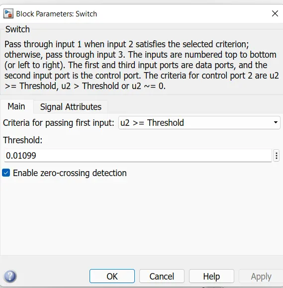
- Therefore the fan conditions are executed by SWITCH block and plotted in scope block.