Week - 4
- Implement control logic of a “washing machine” using Stateflow
Working Prinncple of Washing Machine
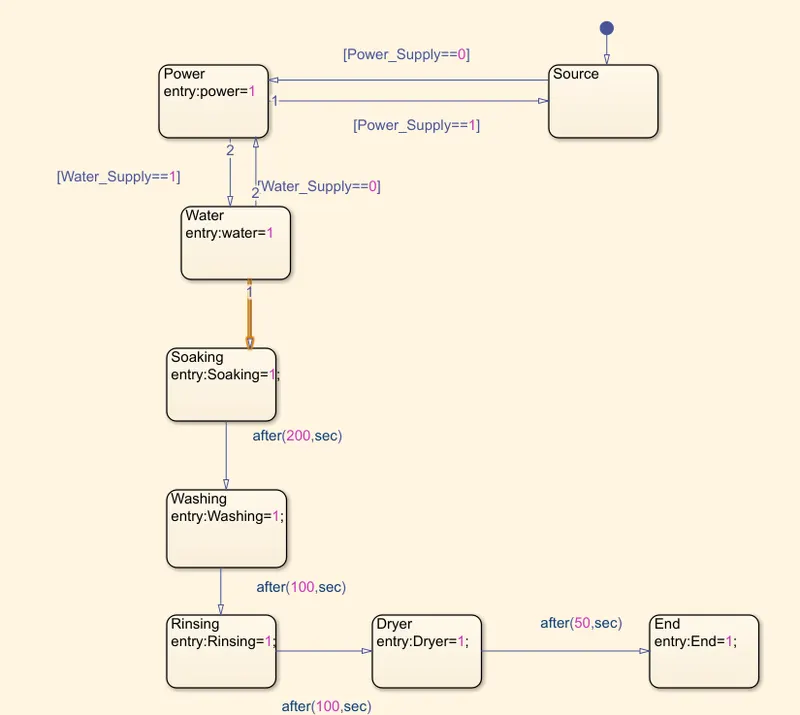
- Power
- Water
- Soaking
- Washing
- Rinsing
- Dryer
- End
Power
- Power is the energy source of washing machie to wash the cloths with the help of motor
- There are different types of motors are used in washing machine but universal motor is widely used motor in this application
Water
- After Turn on the switch of the machine we want to keep our cloths to the drum of the machine
- Then it sense the weight of the cloths and start filling water to the drum depends on the weight and quandity of the cloths
- If the warter not fill in the drum the led light (Lamp) indicate the issue
Soaking
- In Soaking Procces it will soak all the cloths with water and washing liquid
Rinsing
- In this Procces the drum will rotate in clock wise and anticlock direction with the help of universal motor
Dryer
- Heat blower is used in dryer to dry the cloths
End
- After drying the cloths machine indicate that washing was completed through led indication
Simulink Block
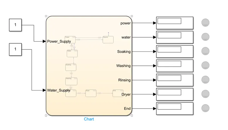
Blocks Used
- Constant
- Chart
- Display
- Lamp
Constant Block
- Constant Block Is used as a Input For power supply and water Supply
Chart
- Chart is used to make a State flow
- Symbols pane is used to configure input and output port of the chart
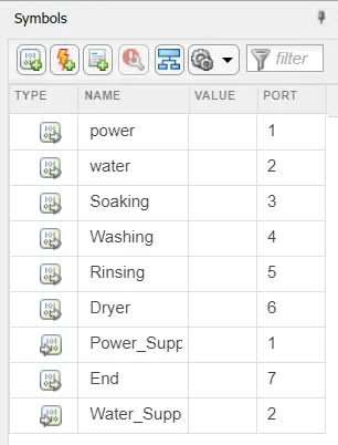
- There are two input port and seven output port
Display
- Display is show the current state of washing machine
Lamp
- Lamp is used to show the state of the machine by blinking the lamp
2. Make a Simulink chart for the “Gear shift” logic as per below conditions:
Speed Range(kmph) Gear
0 to 15 1
16 to 25 2
26 to 40 3
41 to 60 4
Above 61 5
Now We are going to make a simple Gear shif indicator in a simulink
Blocks used
- Constant
- Slider Gain
- Chart
- Display
Constant
- Constant is a block used for input to the slider gain
Slider Gain
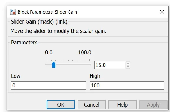
- Slider gain is a block used to change the speed for the input
Chart
Chart block is used to make a state flow
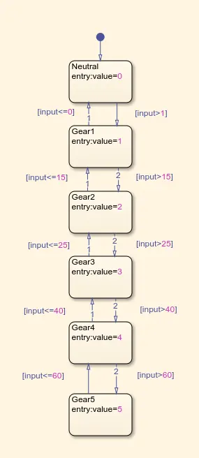
Display
Display is used to show the output here the out the gear
Simulink

Now We can see how the simulink is working
- If the speed range is 0 to 15 kmph then gear is in 1st
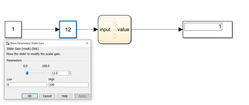
- If the speed range is 16 to 25 kmph then gear should be 2nd
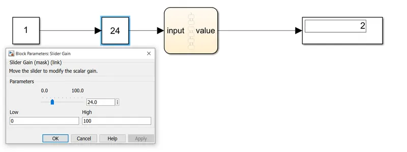
- If the Speed range is 26 to 40 kmph then gear is changed into 3rd
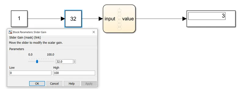
- If the Speed range is 41 to 60 kmph then gear is shifted to 4th
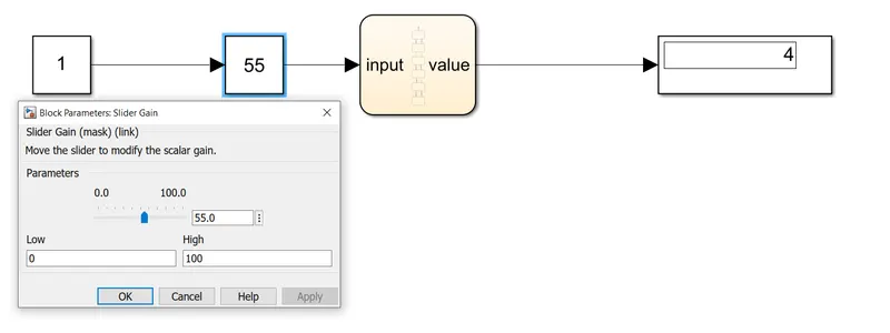
- If the speed range is crossed the 60 kmph then the gear is changed to 5th
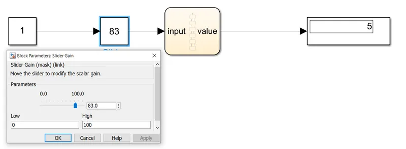
Hence the simulink is completed