Project
What Is ATV
ATV is an abbreviation for all-terrain vehicle, We can ride this vehicle almost all surface Example on roda,off road, stones snows, water crossing and its also have some varients like three wheel and four wheel it is chatriced depend upon CC
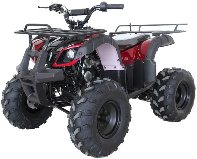
Pic:1 All Terrain Vehicle
- BAJA ATV MODEL WITHOUT DASHBOARD
- BAJA ATV MODEL WITH DASHBOARD
- BAJA ATV MODEL USING LOOKUP VALUE WITHOUT DASHBOARD
- BAJA ATV MODEL USING LOOKUP VALUE DASHBOARD
1.Baja ATV MODEL WITHOUT DASHBOARD
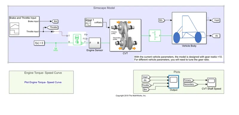
Pic:2 BAJA ATV MODEL
Blocks Used
- Signal Builder
- Slover Configuration
- Generic Engine
- Engine Sensor Subsystem
- CTV Subsystem
- Simple Gear
- Vehicle Body Subsytem
- Goto
- From
- Scope
Signal Bulider
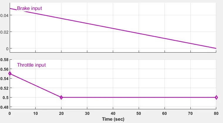
- Signal Builder is used to give the input for the Simulink model in this model we used two signal builder one builder is used to give throttle and break input and another block is used to give CTV ratio
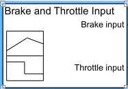
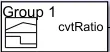
Pic:3 Throttle and Brake Inupt Pic:4 CTV Ratio Input
- You Can Change the inputs By dragging thee vertical line in the Signal Builder block are Shown Below
Solver Configuration
- This block is used to specifie the solver parameters of the model needs before simulation begin,Each Simscape block diagram requires exactly one Solver Configuration block to be connected to it
Generic Engine
- Represents a system-level model of spark-ignition and diesel engines suitable for use at initial stages of modeling when only the basic parameters are available. Optional idle speed and red line controllers are included.
- The throttle input signal T lies between zero and one and specifies the torque demanded from the engine as a fraction of the maximum possible torque. If the engine speed falls below the Stall speed, the engine torque is blended to zero. If the engine speed exceeds the Maximum speed, the simulation stops and issues an error message.
- Connections F and B are mechanical rotational conserving ports associated with the engine crankshaft and engine block, respectively.
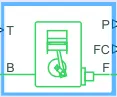
- The input parameters of this block is already assigned is work space


Torque Speed
- Torque and Speed are Inversly proportional to each other
Engine Sensor Sub System
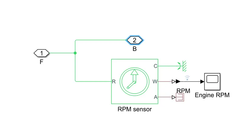
- In engine sensor subsystem we have RPM Sensor , scope, mechanical rotational reference,
Physical Modeling Connection Port block for subsystems,PS Terminator
- RPM Sensor is used to find the rotation and its has four ports
- The ports A is angular velocity W is physical signal ports,port R relative to port C. The measured angular velocity is positive when the angular velocity at port R is greater than the angular velocity at port C.
- scope is used to view the engine rpm in graph formet
- PS terminator is connected to port A and w is connected to scope through PS-simulink converter
- port c is connected to mechanical rotational reference and the port R is connected to pmc ports
CTV Ratio
- It also a signal builder used to give the input ratio for CVT Subsystem
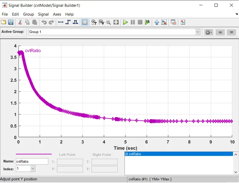
- we can change the input ratio of CVT by dragging the curve shown above
CVT Subsystem
- CVT Means Continuously Variable Transmission
- In this baja ATV model Gear box is replaced by CVT System and this sustem is consist of primary and secondary pulley
- The primary Pulley is directly connected to the crankshaft of the engine and the secondary pulley is connected to drive shaft
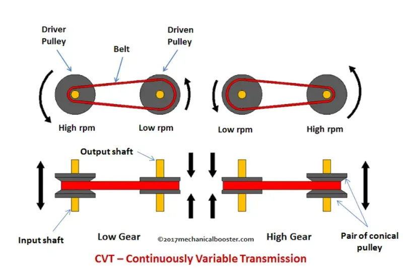
- Pulley means combination of both static and moveable sheave
- The primary and secondary have have its own axle shaft and parallel to each other Infinite gear ratios can be achieved by both pulleys driven by belt while pulleys diameter varies according to the movement of sheaves
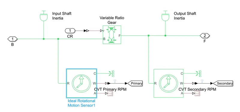
- The CVT System consist of input shaft inertia, variable ratio gear, output shaft inertia, ideal rotational sensor and
Physical Modeling Connection Port block for subsystems
- Ideal Gear rotational motion sensor has The ports A is angular velocity W is physical signal ports,port R relative to port C. The measured angular velocity is positive when the angular velocity at port R is greater than the angular velocity at port C.
- And is worked as primary and secondary pulley
- In variable gear ratio output shaft rotates in same direction as input shaft and the ports base is connected to primary pulley and follower is connected to secondary pulley
Simple Gear
- Simple Gear block represent the Fixed gear ratio and in this block we can not change the inertia and compliance
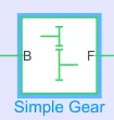
- Connection B is base and F is follower are mechanical rotational conserving ports and port B is connected to CVT subsystem and F port is Connected to Vehicle body Subsystem
Vehicle Body Subsystem
- This subsystem consist of tire(magic formula),vehicle body integrator,PS Constant,double shoe break,inertia output shaft
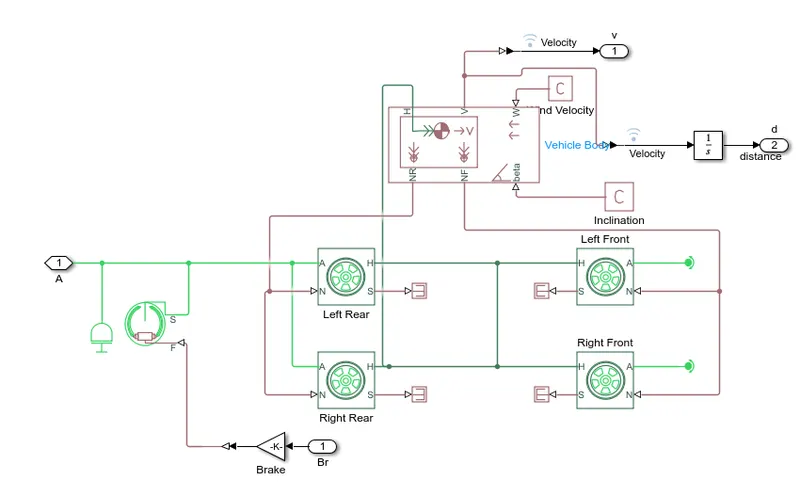
- In tire block there are four ports H is Hub S is Tire Slip N Is a normal force applied to the tire A is Axel connection
- the vehicle body block consist of six ports NR is a normal force and its is connected to rear wheels and NF is also normal force and its connceted to front wheels
- Beta is the Up Hill or slop Angle And W is the wind velocity and this two ports are connectd to PS Constant we not Give any Specific Value
- V is the Velocity of the vehicle and H Is the Hub Of the Body the Vehicle body hub is connected to hub of the four tire axel
GOTO AND FROM BLOCKS
- Goto Block is used to send signal to from block
- From block is used to recive signals form Goto block with Specified name tag
2.BAJA ATV MODEL WITH DASHBOARD
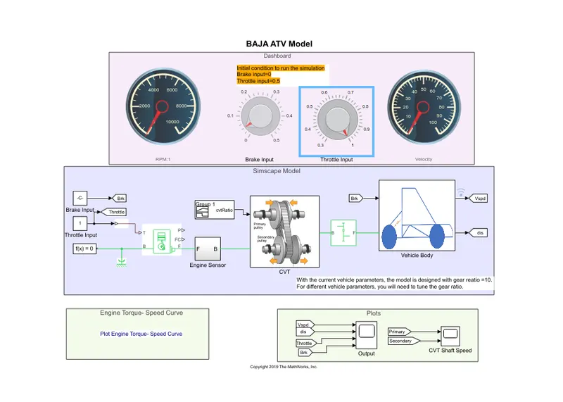
- The Below figure shows the BAJA ATV with dashboard and it replace the signal builder with dashboard we can give input throttle and break input with the help of dashboard
- other wise the block and subsystem are same as the above ATV model without dashboard
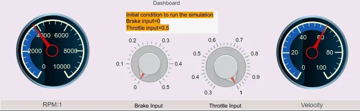
- By using dashboard we can understand the result by varying input of throttle and brake
- The break input varies from 0 to 0.5 and the throttle varies from 0.3 to 1
- while changing the throttle input or brake input the RMP meter and velocity meter show the change of speed and rmp in the vehicle
3.Baja ATV MODEL USING LOOKUP VALUE WITHOUT DASHBOARD
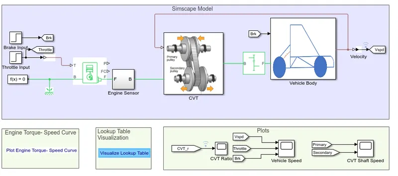
- The working of this Model is same as model 1 but in this model we have extra futhure that is lookup table other wise the working of block and subsystem are same Signal Builder,Slover Configuration,Generic Engine,Engine Sensor Subsystem,Simple Gear,Vehicle Body Subsytem Except the CTV Subsystem
- Lookup table blocks use arrays of data to map input values to output values, approximating mathematical functions. To approximate a function in N variables
- A look up operation retrieves the corresponding output values form the table if the look up table does not explicitly define the input values
- simulink can estimate an output value using interpolation,extrapolation,or rounding
- Estimate values that lies between known data is interpolation
- Estimate value that lie beyond the range of known data point is known as extrapolation
- Approximating a value bt altering its digits according to known rule is known as Rounding
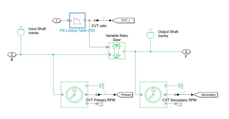
- The CVT System consist of input shaft inertia, variable ratio gear, output shaft inertia, ideal rotational sensor and
Physical Modeling Connection Port block and PS lookup table for subsystems
- Ideal Gear rotational motion sensor has The ports A is angular velocity W is physical signal ports,port R relative to port C. The measured angular velocity is positive when the angular velocity at port R is greater than the angular velocity at port C.
- And is worked as primary and secondary pulley
- In variable gear ratio output shaft rotates in same direction as input shaft and the ports base is connected to primary pulley and follower is connected to secondary pulley
- variable ratio gear port b is connected to primary pully and input shaftinertia
- And port F is connected to secondary pulley and out put shaft inertia
- port r is connected to PS look up table
4.BAJA ATV MODEL USING LOOK UP VALUE WITH DASHBOARD
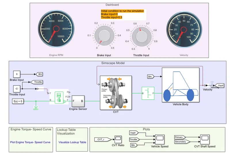
- The shows figure shows the BAJA ATV using look up value with dashboard and it replace the signal builder with dashboard we can give input throttle and break input with the help of dashboard
- other wise the block and subsystem are same as the above ATV model using look up value without dashboard
- By using dashboard we can understand the result by varying input of throttle and brake
- The break input varies from 0 to 0.5 and the throttle varies from 0.3 to 1
- A look up operation retrieves the corresponding output values form the table if the look up table does not explicitly define the input values
- simulink can estimate an output value using interpolation,extrapolation,or rounding
- Estimate values that lies between known data is interpolation
- Estimate value that lie beyond the range of known data point is known as extrapolation
- Approximating a value bt altering its digits according to known rule is known as Rounding
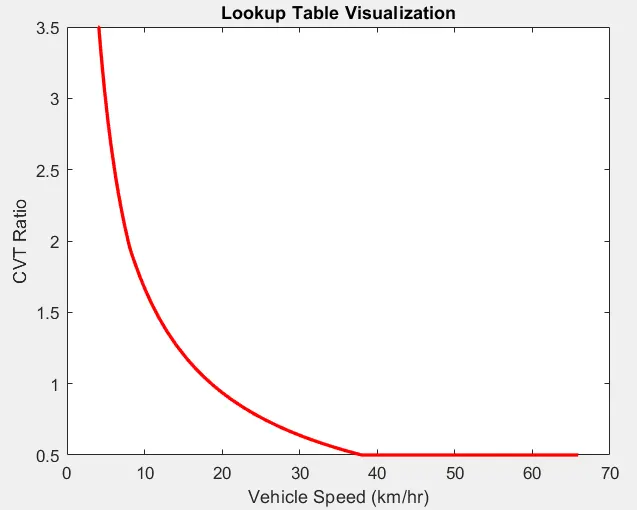
OUTPUT
1.Baja ATV MODEL WITHOUT DASHBOARD
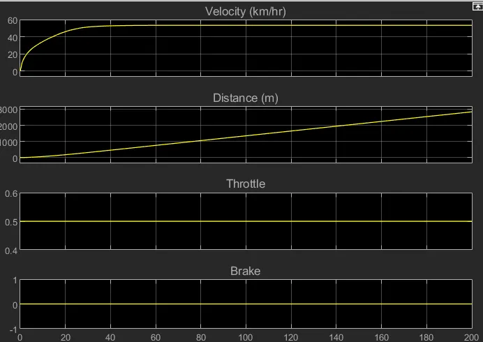
- In above figure shows the output while we maintain the brake at zero and throttle at 0.5
- The vehicle covered 8000m in the period of 200sec
- The velocity of the vehicle increasing graudly after certain period of time it reach 50km/hr
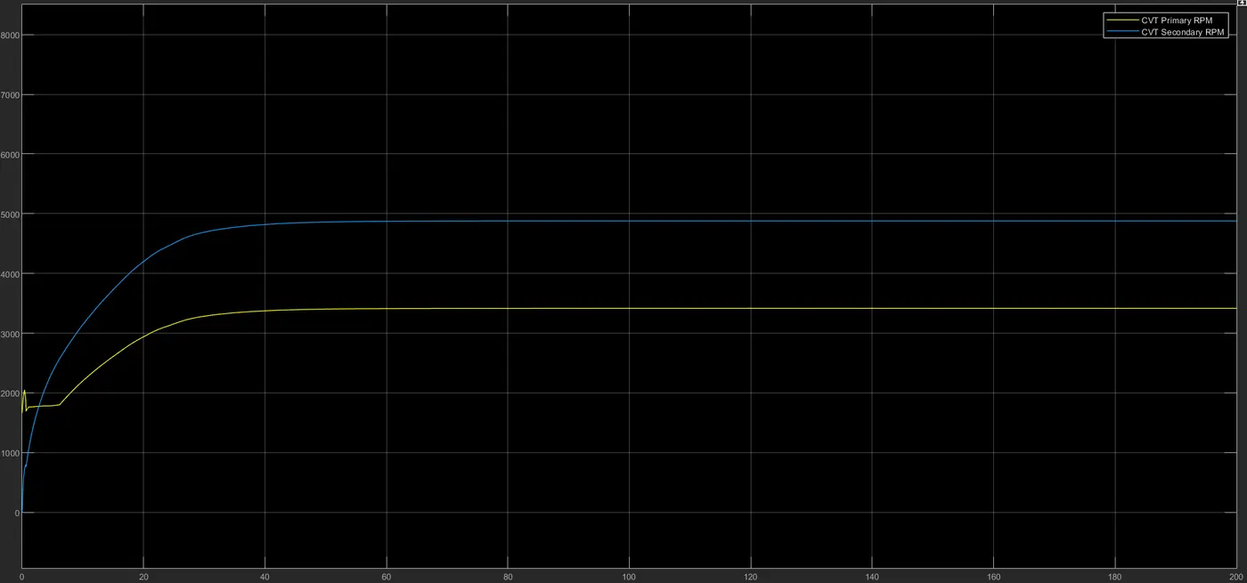
- The above graph show the ouput of the primary and secondary rpm of CVT the blue line represent the secondary rpm and yellow line represnt the primary rpm of Cvt
2.BAJA ATV MODEL WITH DASHBOARD
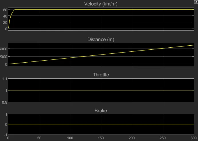
- Through the help of dashboard we can easyly change the input of brake and throttle
- depends upon the throttle and brake the distance and velocity will change
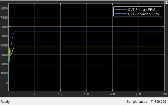
- The above graph show the ouput of the primary and secondary rpm of CVT the blue line represent the secondary rpm and yellow line represnt the primary rpm of Cvt
3.Baja ATV MODEL USING LOOKUP VALUE WITHOUT DASHBOARD
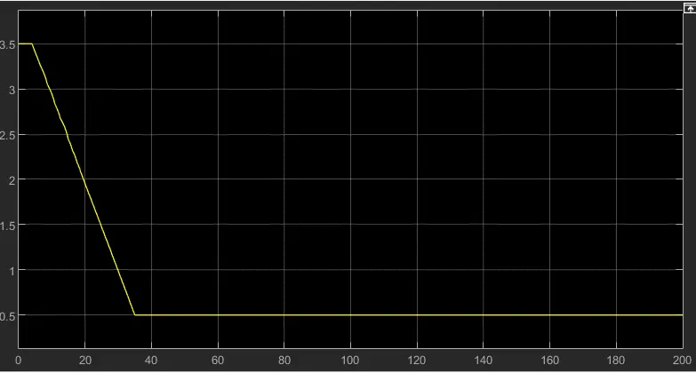
- The above graph show the CVT Ratio
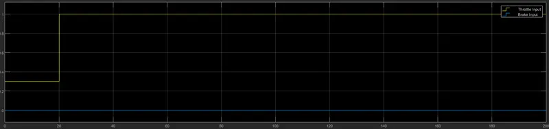
- the above graph show the insput of throttle and brake to the model
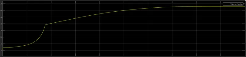
- The above graph show the ouput of the model veloctiy the top seepd was 65 km/hr
4.BAJA ATV MODEL USING LOOK UP VALUE WITH DASHBOARD
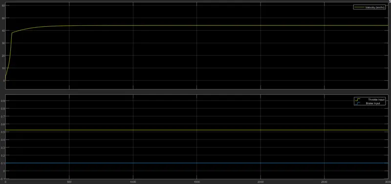
- The Above graph shows the input of throttle and brake and the ouput in terms of velocity
- the maximum velocity of the input is 45km/hr
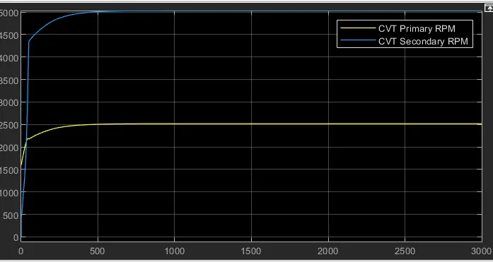
- The above diagram shows the output rpm of primary and secondary CVT