Week - 4
1.
Stateflow chart:
Model:
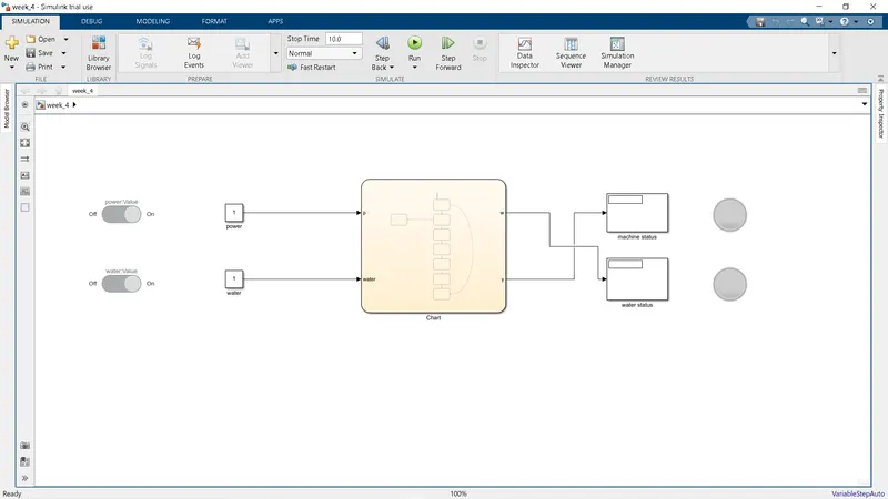
Explanation:
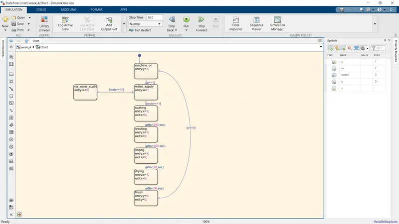
- To create a stateflow chart, a chart block is used.
- In the chart number of states are used as required and a name is given to it.
- The entry or exit commands are used to determine the entry or exit of the state.
- Each state are connected using arrows and each arrow has a command that determines the path of the stateflow.
- In this model, control logic of a “washing machine” using Stateflow as per given sequence is created.
- A washing machine has 4 stages: soaking, washing, rinsing and drying.
- Time for each stage is given and are used as commands for the arrows using the after command.
- Here, the inputs are water and power supply and the outputs display the machine on or off status and the water supply status.
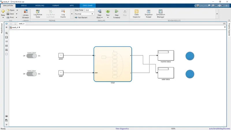
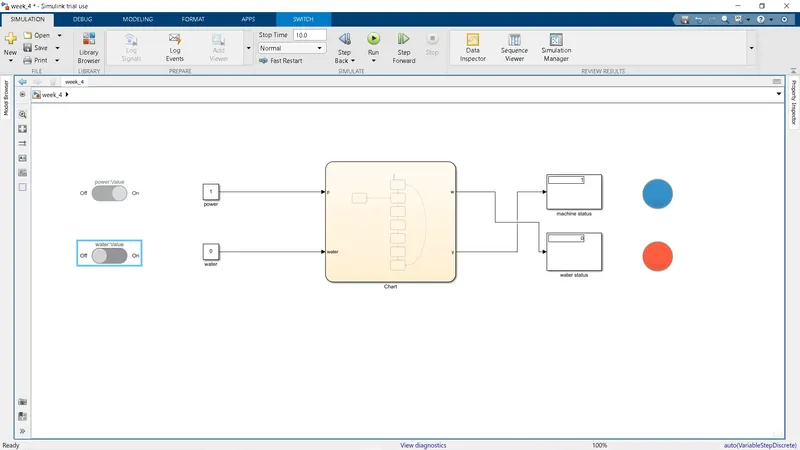
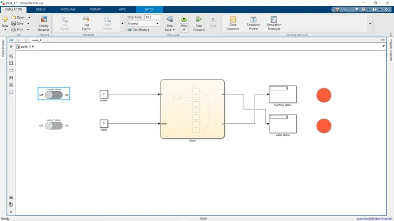
- The inputs are controlled using a slide swutch and the outputs are displayed by a lamp block which turns blue when on and red when off as shown in the below figures.
Output:
all on:
water supply off:
all off:
2.
Stateflow chart:
Model:
Explanation:
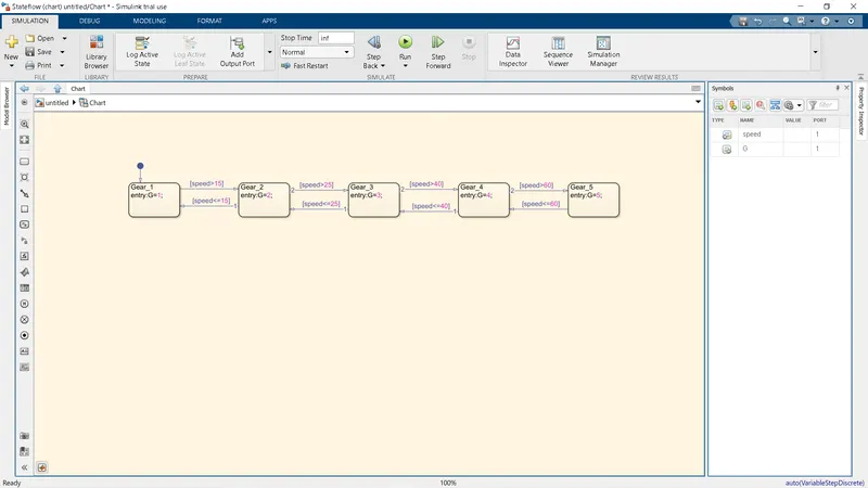
- To create a gear shift logic, a stateflow chart is used.
- In the chart block, five states are used named from gear 1 to 5.
- The arrows have commands according to the speed given.
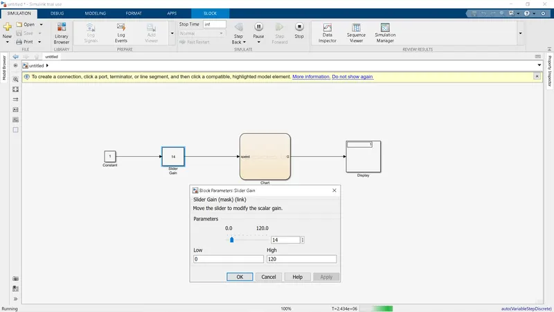
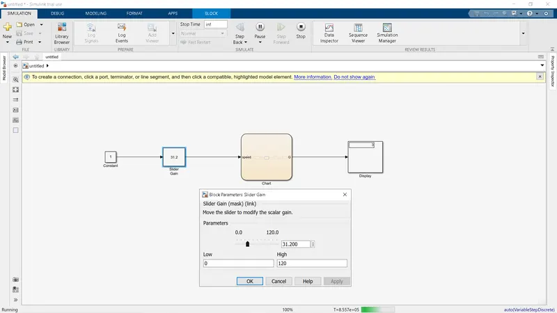
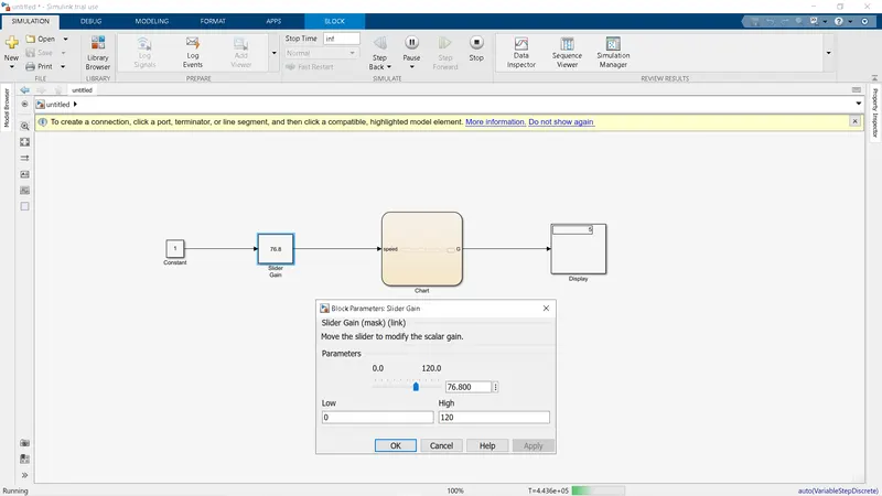
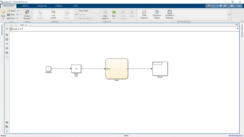
- The input is speed determined by a slider gain block and output is connected to a display block that shows the gear number at that speed.
- The outputs for different speeds are shown as the figures below.
Output at Different speeds: