Week - 4
Task-1
Aim: To Implement control logic of a “washing machine” using Stateflow.
conditions :
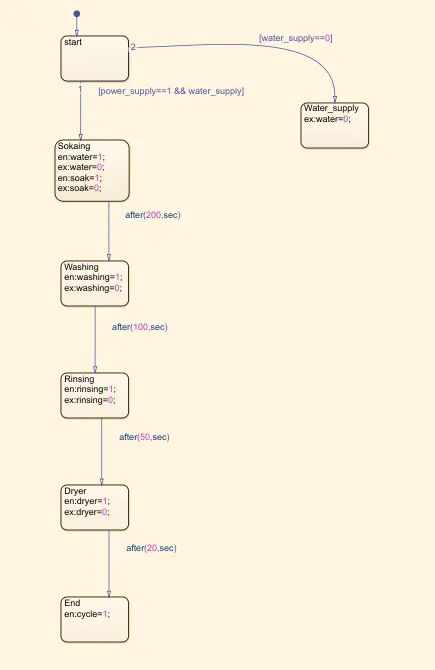
- If the power supply is available, the system gets activated
- If the Water supply is not available, stop the process & indicate through LED
- Soaking time should be 200s followed by Washing time of 100s.
- Then rinsing happens for next 20s & dryer runs for 50s
Input model data:
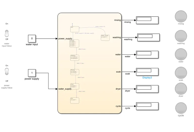
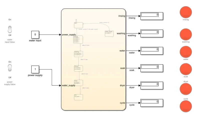
flowchart:
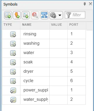
value define in symbols:
here, we have defined rinsing, washing, water, soak,deyer,cycle as an output data.
also power_supply and water_supply as an input data.
simulation time:
we also have to increase the simulation time, this time should be such that all cycle must be completed and computed hence we have taken 450sec
output:
1)according to the first condition ie ,power supply and water suplly is available, the system gets activated
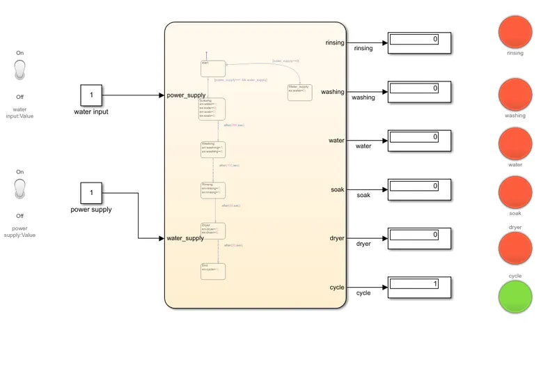
parameteres:
we have given the inputs value 1 as green and 0 as red to the lamp block.
result:
red indicates that the work is completed.
green indicates the work is in progress
hence we can say that task has been completed and green indicates process completion named as cycle.
2) according to the second condition ,ie when water supply is off and power supply is on.
result:
As all of the lamps indicates the red signal hence he can say that when their is no water supply then all of other actions get terminated.
conclusion :
The working of the washing machine flowchart is exicuted and the results are according to the given condition.
#######################################################################################################################
Task-2
Aim : To Make a Simulink chart for the “Gear shift” logic
conditons:
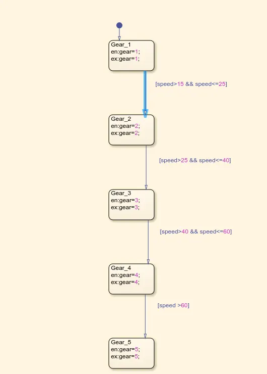
Speed Range(kmph) Gear
0 to 15 1
16 to 25 2
26 to 40 3
41 to 60 4
Above 61 5
Give speed input while the simulation is running & display the gear number.
Input chart model:
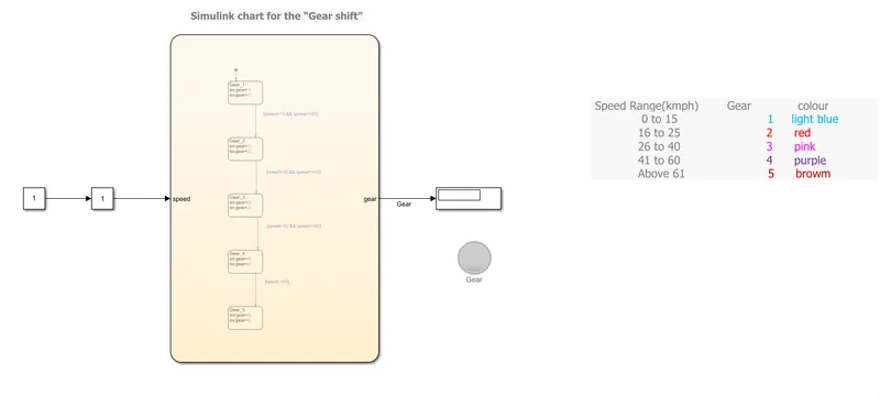
flowchart:
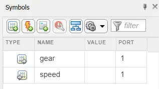
input and output data of flow chart are defined in symbols tools.
we have a speed as an input data and gear as an output data.
simulation time:
simulation time is set to inf as to record the output at the variable input values of speed .
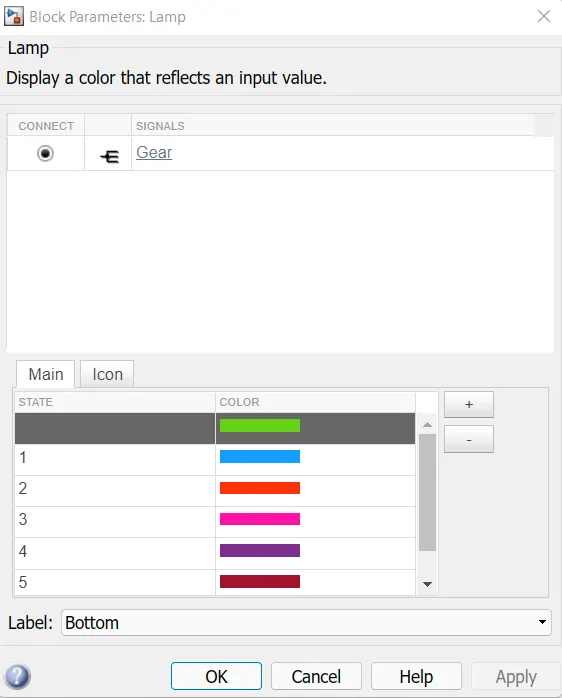
lamp input :
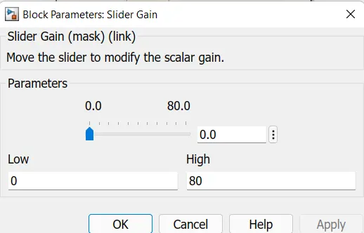
slider input:
Output:
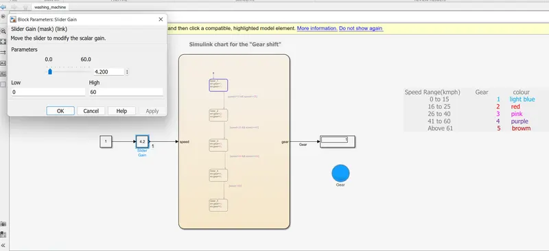
1)
speed range -0 to 15
input speed-4.20
colour-light blue
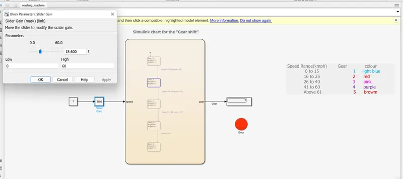
2)
speed range -16 to 25
input speed-18.60
colour-red
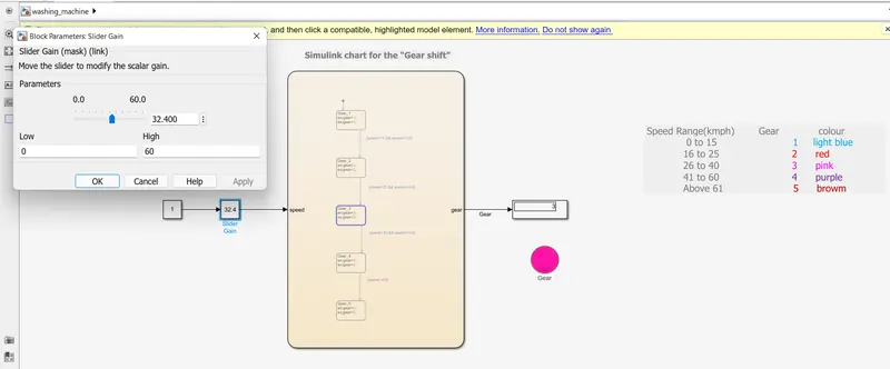
3)
speed range -26 to 40
input speed-32.40
colour-pink
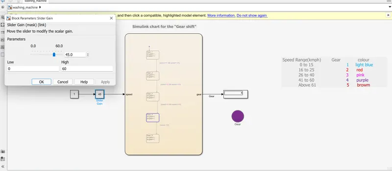
4)
speed range -41 to 60
input speed-45.0
colour-purple
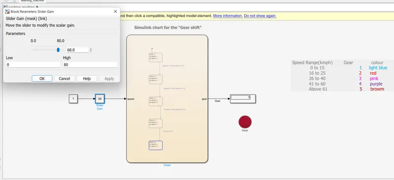
5)
speed range -more than 60
input speed-68.0
colour-brown
Conclusion: gear shift simulink chart is performed and the results are satisfactory.