Week - 4
- Implement control logic of a “washing machine” using Stateflow as per given sequence:
- If the power supply is available, the system gets activated
- If the Water supply is not available, stop the process & indicate through LED
- Soaking time should be 200s followed by Washing time of 100s.
- Then rinsing happens for next 20s & dryer runs for 50s
After all the processes have completed turn on the finished LED
Working principle of a washing machine
A washing machine spins at 800-1600 rpm, allowing detergent and grime to leave the surface of the fabric by centrifugal force and into outlet pipes, employing centrifugation to both clean and partially dry the garments put in it. As a result, the drum, valves, pump, motor, and heaters are all electronically controlled. The valve is reopened, and the unclean water drains from the drums. The pump operates to assist remove the water. The valve allows clean water to enter the drums once more. The four processes are as follows:
- soaking
- washing
- rinsing
- drying
stateflow is a sequential, clear, and realisable finite process step set that allows for systematic issue solving. This set is known as a "algorithm," and it is one of the most fundamental components of programming languages. This research shows how to train an algorithm using Simulink Statcflow. Algorithm learning using flow diagrams.
Control logic for washing machine
It examines the quantity of filth and grease, the amount of soap and water to be added, the spin orientation, and so on. To guarantee proper spinning, the machine rebalances the washing load. If an imbalance is identified, it slows the spinning speed. Spinning noise is reduced when the washing load is distributed evenly.
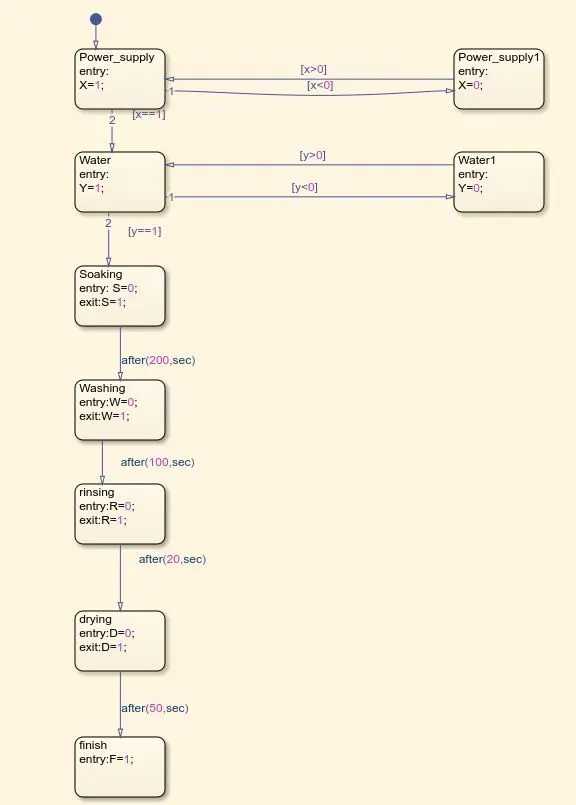
Figure 1: control logic of washing machine using Stateflow
Give the input values for turning the Power Supply and Water Supply on or off. Condition:
If value =1, Power and Water Supply will turn ON. If value = 0, Power and Water Supply will turn OFF using Lamp block.

Figure 2: input and output variables
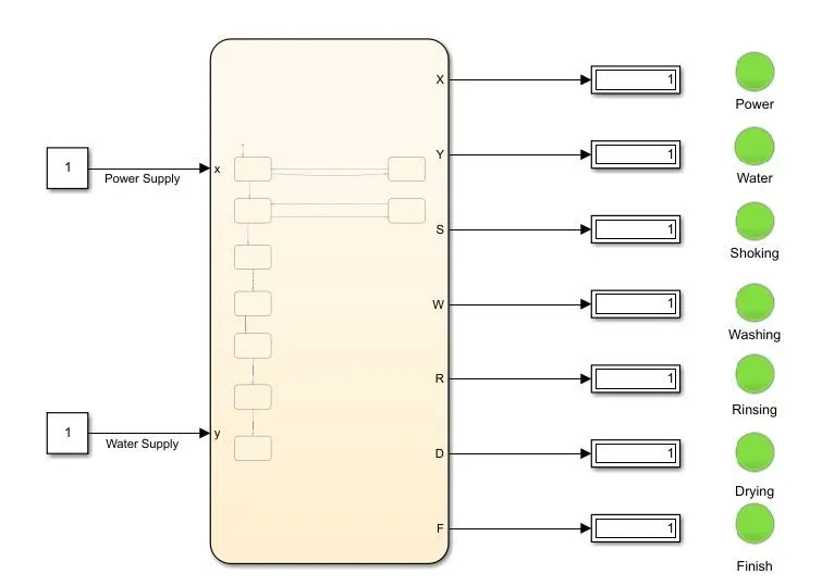
Figure 3: Simulink model of washing machine with stateflow
There are two inputs for electricity and water supply. Once the inputs are entered, the flow chart displays the outputs in the order specified. The system is watched for a period of time before being examined, and the procedure is finished by the display of a green light.
2. Make a Simulink chart for the “Gear shift” logic as per below conditions:
Speed Range(kmph) Gear
0 to 15 1
16 to 25 2
26 to 40 3
41 to 60 4
Above 61 5
Give speed input while the simulation is running & display the gear number.
A manual transmission gear shift system features an axially moveable shaft for choosing shift planes and a rotating shaft for engaging the gears defining the shift planes. Two helical springs keep the shaft in a reference shift plane.
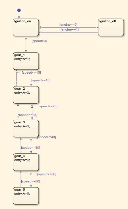
Figure 4: Simulink chart for the Gear shift logic
The Stateflow chart takes two inputs: speed and engine. The speed input is linked to a constant called slider block, acts as a Accelerator speed, while the engine input is linked to a constant called Ignition ON/OFF. The constant Ignition ON/OFF is linked to a slider switch. Here engine is used as an input in the Stateflow chart, Checking ignition condition. Giving the condition engine==O means that it will run when the constant value is 0, indicating that the car is switched off, and giving another condition engine==1 means that it will execute when the constant value is 1, indicating that the vehicle is turned on. When the ignition condition is activated, the state transitions to the following procedures. Each block has its own set of speed conditions. When the pace of the process increases, the condition of the process moves to the next block. Each block has been assigned all of the criteria. The output of the Stateflow chart is labelled "A," and it is attached to a display block. Gear indicator is the name of the display block that is attached to the output.
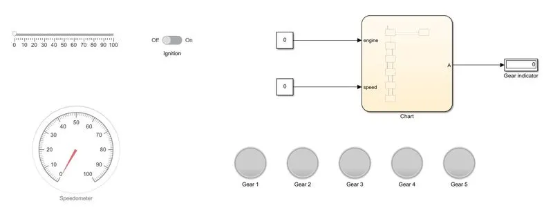
Figure 5: smimulink model of gear shift logic
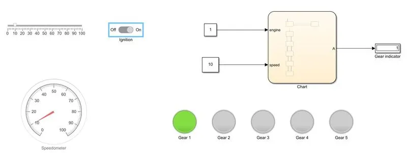
Case 1
When speed is 10 kmph the gear indicator is 1
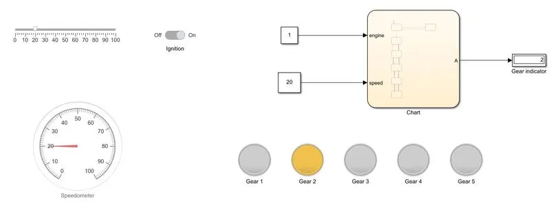
Case 2
When speed is 20 kmph the gear indicator is 2
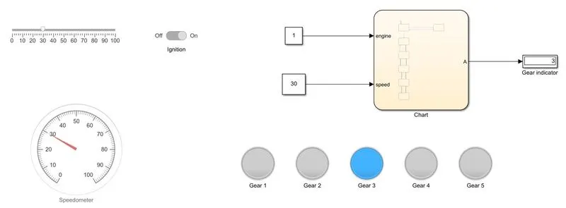
Case 3
When speed is 30 kmph the gear indicator is 3
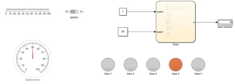
Case 4
When speed is 50 kmph the gear indicator is 4
Case 5
When speed is 65 kmph the gear indicator is 5
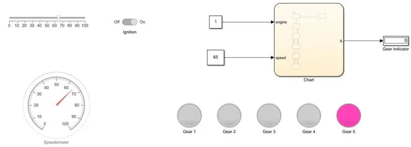
So, The simulation of gear shifts matching to the supplied speed range was successful according to the condition.