Week - 4
Q1. Implement control logic of a “washing machine” using Stateflow as per given sequence:
- If the power supply is available, the system gets activated
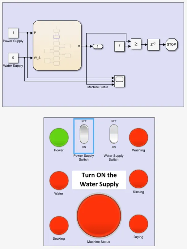
- If the Water supply is not available, stop the process & indicate through LED
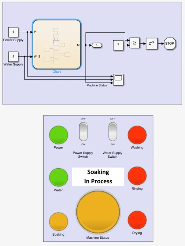
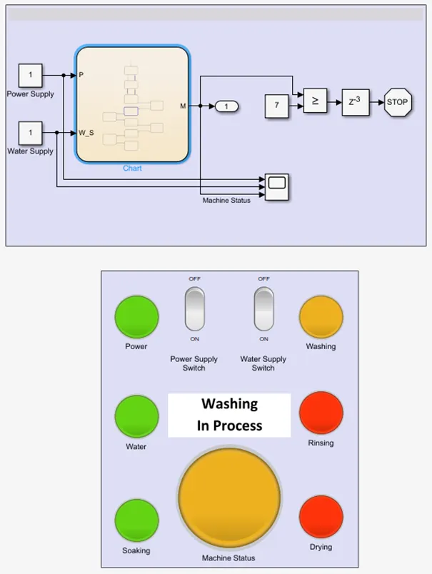
- Soaking time should be 200s followed by Washing time of 100s.
- Then rinsing happens for next 20s & dryer runs for 50s
After all the processes have completed turn on the finished LED.
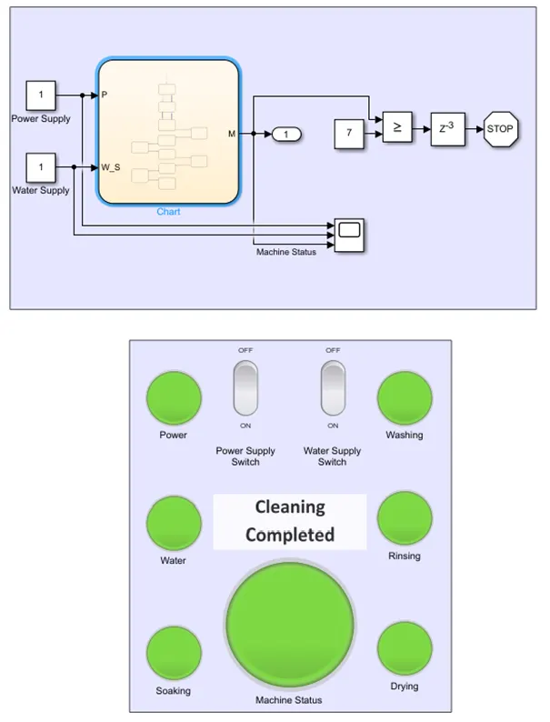
ANS. Simulation model for the washing machine applying control logic:
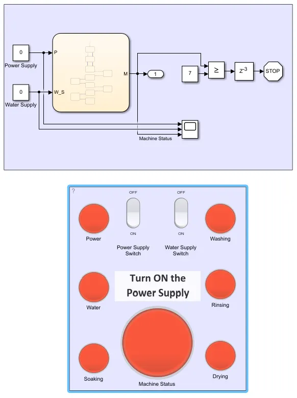
Working of the simulation model :
- Two inputs & single output needed to complete the control logic.
- Input signals are required for power & water supply and the output port is to know the machine status.
- Using constant block, the input signals are provided using the rocket switch block which is the power supply switch & water supply switch.
- For the machine to work under control logic sequence, using the StateFlowChart block which acts based on the given inputs.
- Depending on the inputs, the control logic transition from one state to another.
- Control logic created in StateFlowChart shown below works according to sequence.
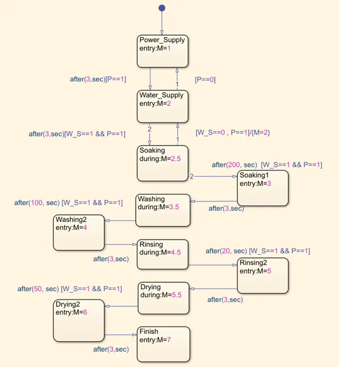
- The control logic as follows:
- First, checking the input of the power supply and displaying the signal according to the input.
- After 3 secs of getting power supply, next state was to check the water supply.
- Then, transition to next state of soaking, where it also checks the water & power supply.
- After soaking process is completed for 200 secs, shift to washiing process with 3 secs delay.
- All following states are achieved to the given sequence and for each state transition power & water supply are checked.
- From the control logic stateflowchart, collecting the machine status as output.
- After completion of these processes, check using a relational operator that stops the simulation with a 3 sec delay.
- In the scope, recording the inputs and machine status with time.
RESULTS :
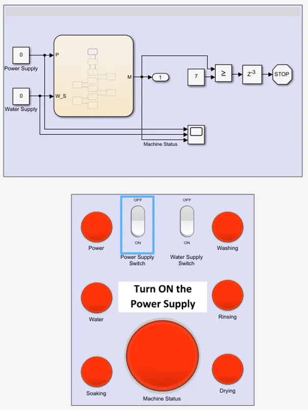
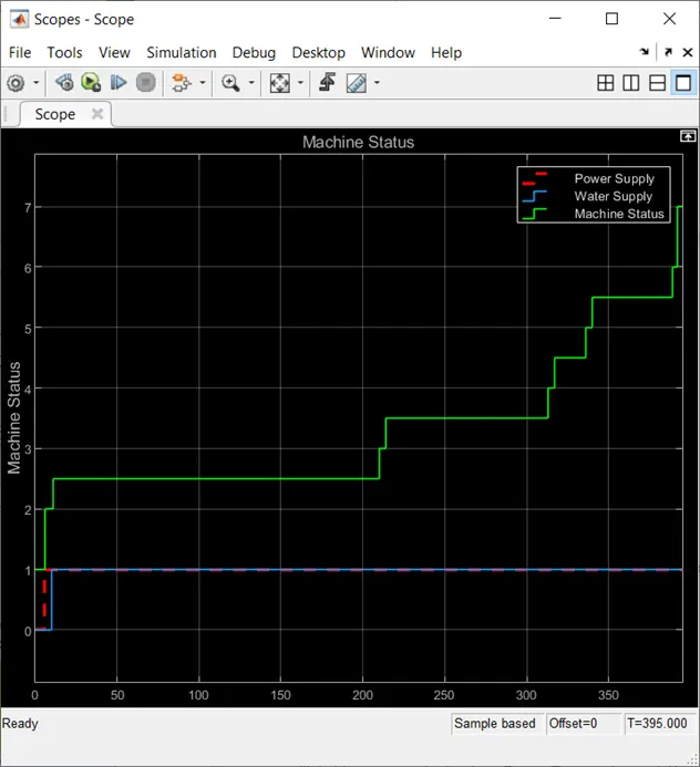
Below, the results of simulation sequentially with time.
1. Power Supply
2. Water Supply
3. Soaking Process
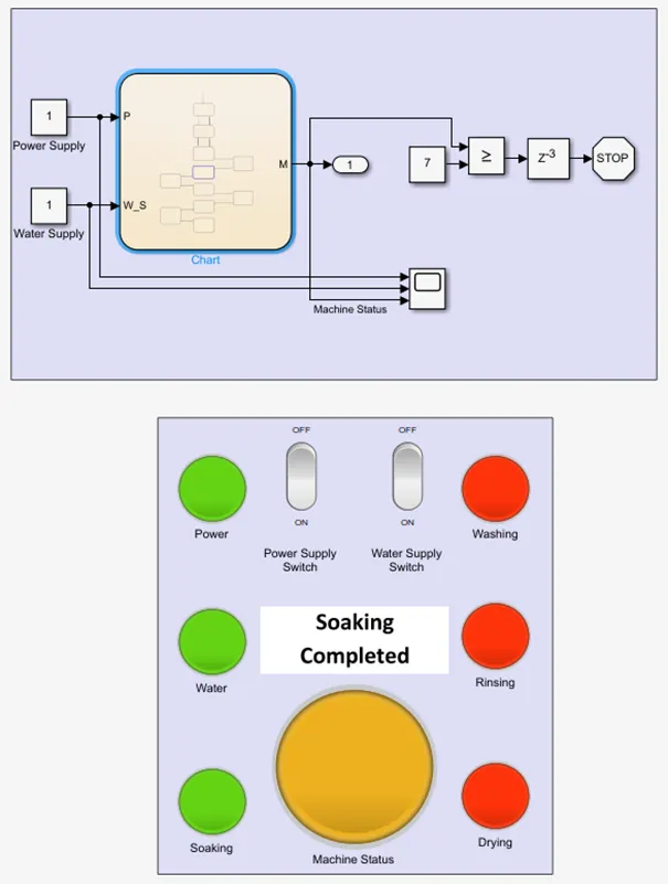
4. Washing Process
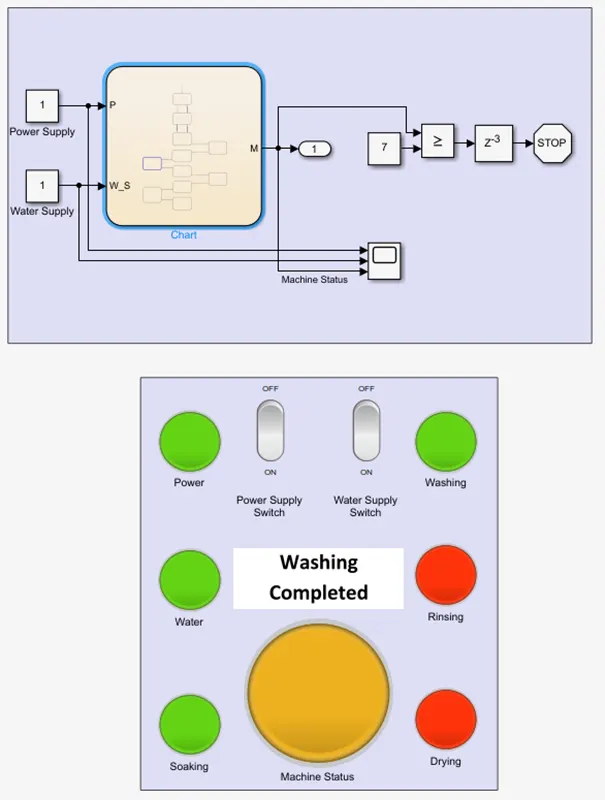
5. Rinsing Process
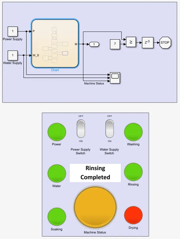
6. Drying Process
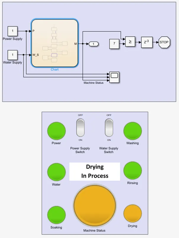
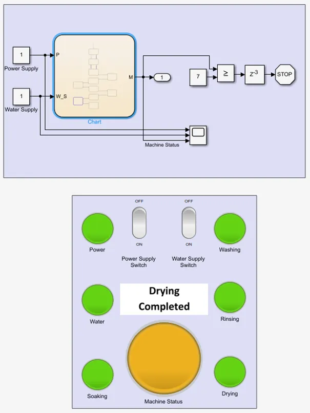
7. FINISHED PROCESS
SCOPE
2. Make a Simulink chart for the “Gear shift” logic as per below conditions:
Speed Range(kmph) Gear
0 to 15 1
16 to 25 2
26 to 40 3
41 to 60 4
Above 61 5
Give speed input while the simulation is running & display the gear number.
ANS.
SIMULATION MODEL
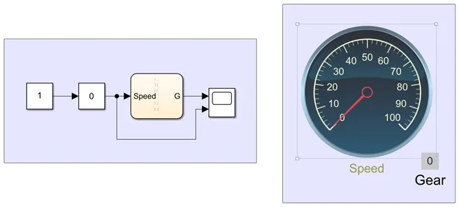
Working of the model:
- This is a 5 speed gear system that has control logic where it checks the speed and changes the gear accordingly.
- StateFlow Chart for the gear system:
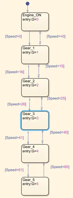
- Input speed is given while the simulation is running, the stateflowchart runs the control logic and changes the gear according to the given speed input.
- Output value collected from the chart
- 2 blocks and circular gauge and display blocks represent the input speed and gear value
- After simulation, with changing speed values using slider gain, checking it's respective gear
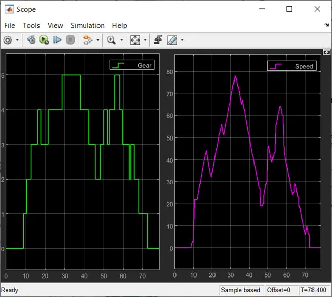
- Using scope block to record speed input and gear output for entire simulation
SCOPE: