Week - 4
AIM:
- To implement control logic create a Simulink chart for the operation of a Washing Machine and Shifting of a Gear by following the required conditions.
OBJECTIVE:
- To implement control logic of a “washing machine” using State flow as per given sequence:
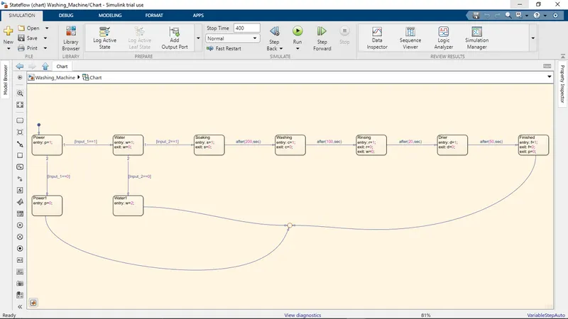
- If the power supply is available, the system gets activated
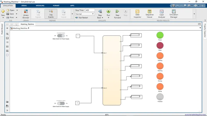
- If the Water supply is not available, stop the process & indicate through LED
- Soaking time should be 200s followed by Washing time of 100s.
- Then rinsing happens for next 20s & dryer runs for 50s
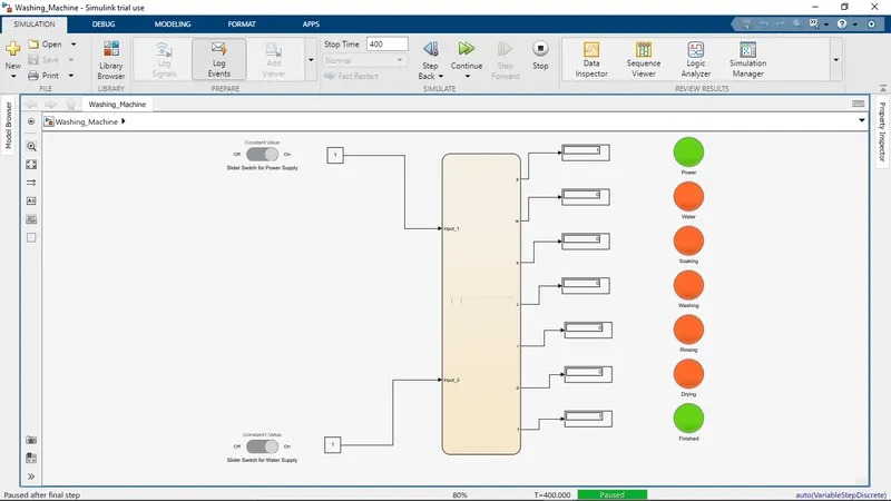
- After all the processes have completed turn on the finished LED
- To make a Simulink chart for the “Gear shift” logic as per below conditions:
Speed Range(kmph) Gear
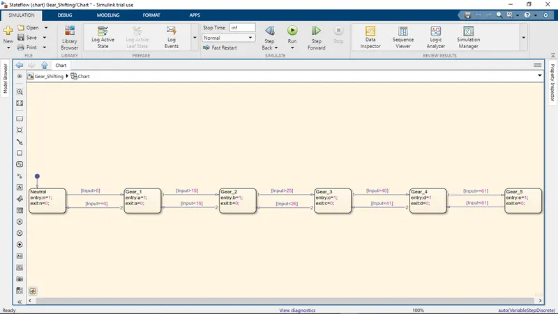
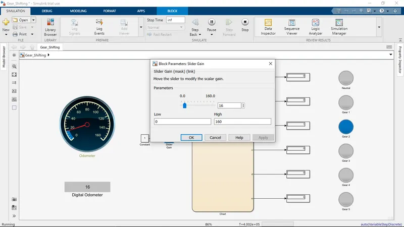
0 to 15 1
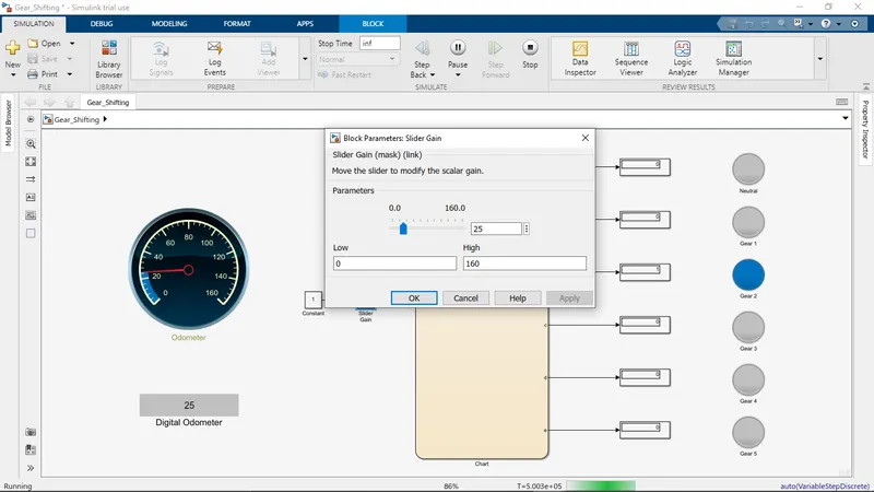
16 to 25 2
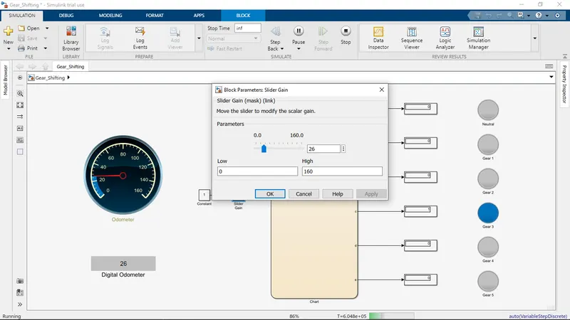
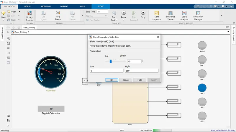
26 to 40 3
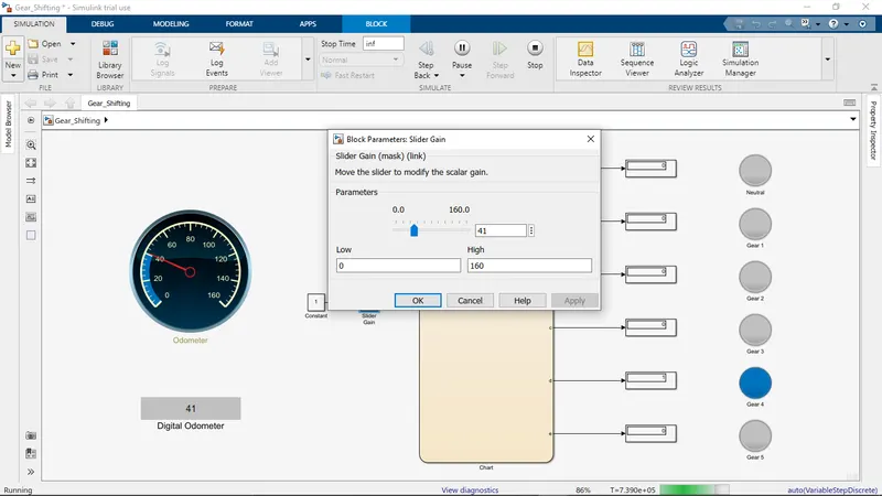
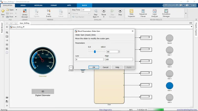
41 to 60 4
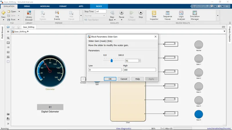
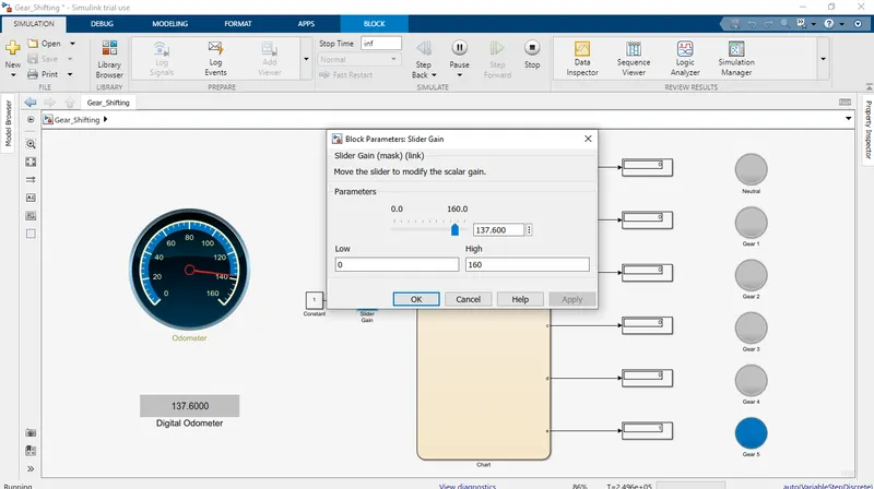
Above 61 5
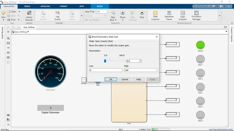
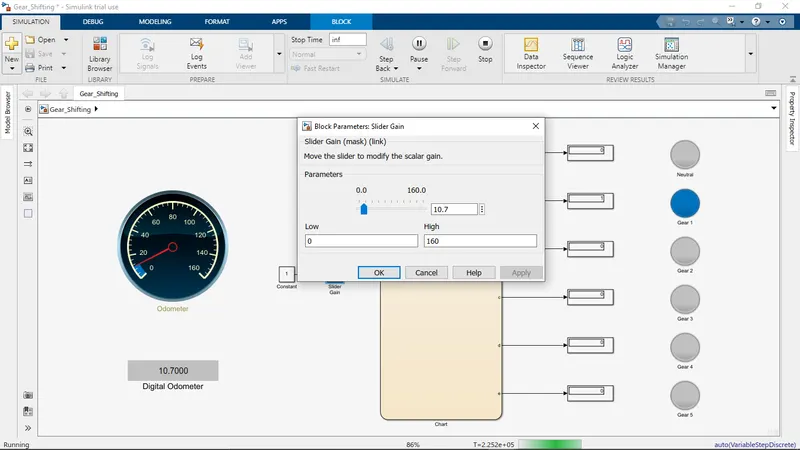
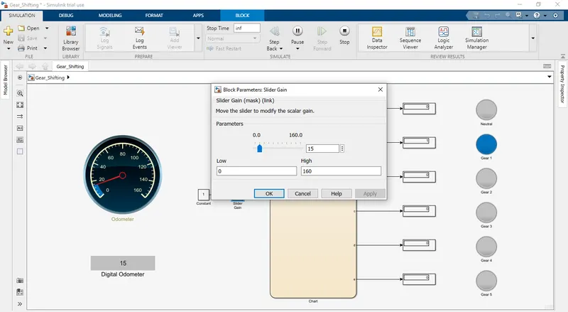
- To give speed input while the simulation is running & display the gear number.
SOLUTION METHODOLOGY:
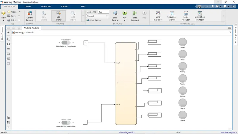
- To implement control logic of a “washing machine” using State flow as per given sequence:
BLOCKS USED:
1. Slider Switch:
- Slider Switch is used to set an ON or OFF value to tune the parameters.
- Here we have used two Slider switches, one is to supply power i.e. Power ON/OFF and the other is for Water supply i.e. Water Supply ON/OFF.
2. Constant:
- To connect our slider switches so that we can get the value for On and OFF.
- For ON state it gives a value of 1 and for OFF state it gives a value of 0.
3. Chart:
- To create our logic for the working of the Washing Machine as per the given conditions.
- The logic for the washing machine to work is implemented using State Flow blocks.
4. Display:
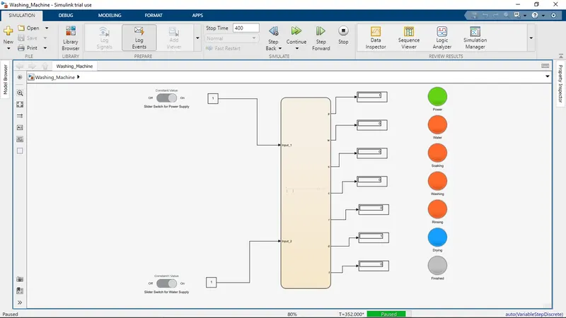
- To display the output of the charts created and to observe the operation going on at present.
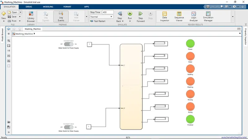
- It displays which operation is going on and which operation is finished.
5. Lamp:
- It displays the color that reflects a value.
- It is used to check the state of the process like which operation is going on at present and which one is completed.
RESULT:
1. WHEN POWER AND WATER SUPPLY IS ON:
STEP WISE:
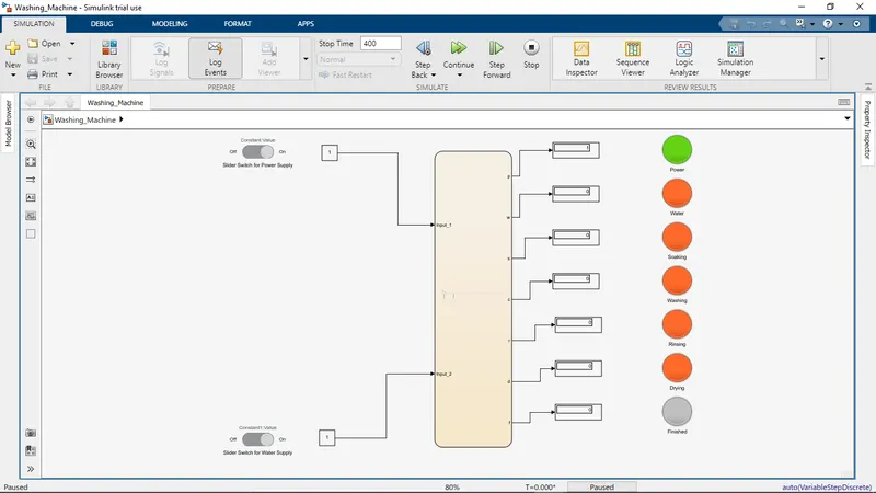
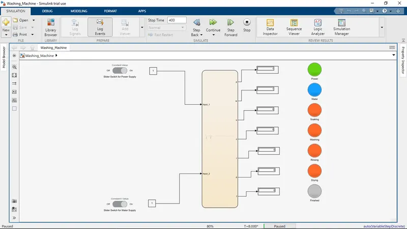
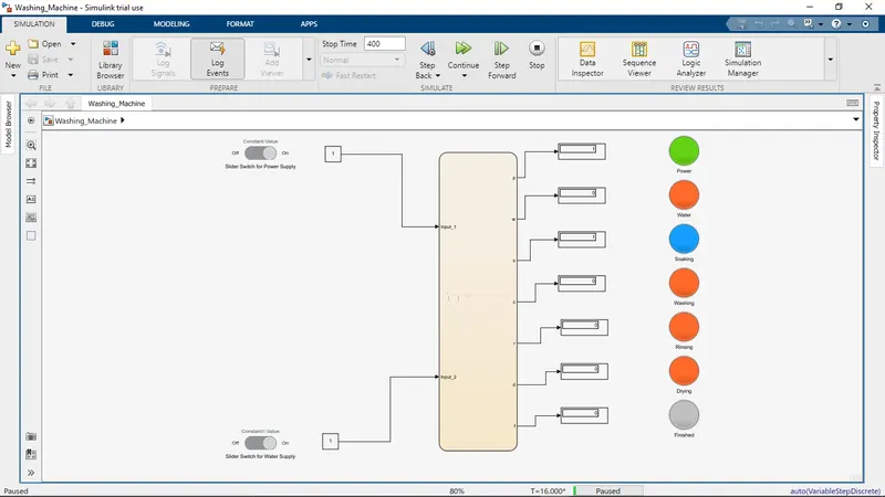
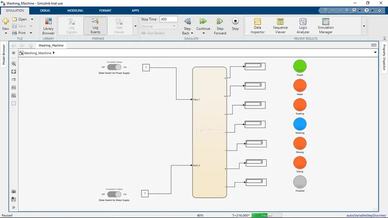
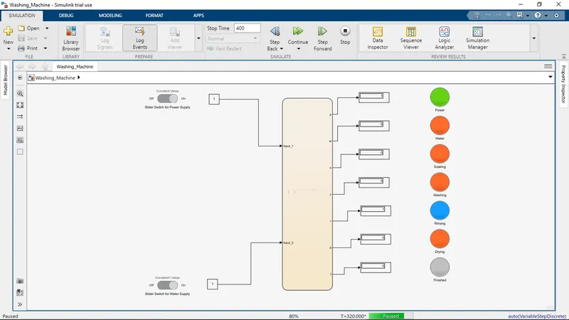
2. WHEN WATER SUPPLY IS NOT AVAILABLE:
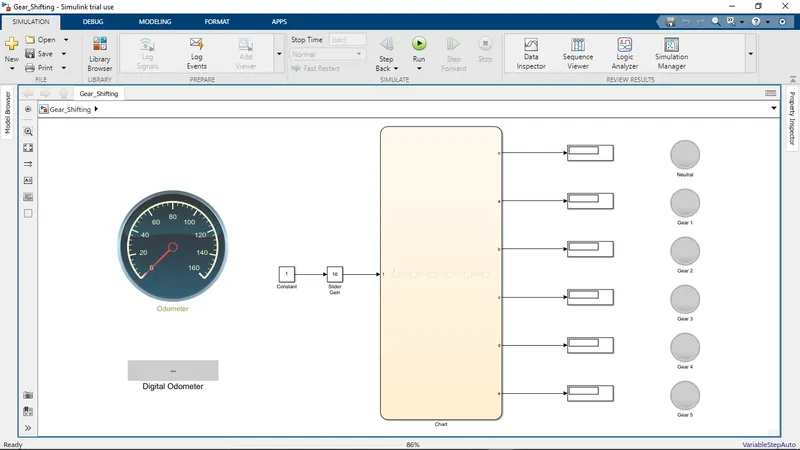
- To implement control logic of a “Gear Shifting” using State flow as per given sequence:
BLOCKS USED:
1. Circular Gauge:
- It is used to display an input in a gauge.
- Here we have used it to display the speed that we give as the input.
2. Display Gauge:
- Used to display the speed input in a digital format.
3. Slider Gain:
- The Slider Gain block performs a scalar gain that you can modify during simulation. Modify the gain using the slider parameter.
- We have used to vary the speed while the simulation is running by sliding from the set range.
4. Constant:
- Used to give input to the Slider Gain as a multiplication factor.
- We have set the value as 1 so that the value we set in the slider gain will be the same.
5. Chart:
- To create our logic for the shifting of the Gear as per the given conditions.
- The logic for the Gear to shift is implemented using State Flow blocks.
6. Display:
- To display the output of the charts created and to observe the Gear number at which the vehicle is running for the input speed at present.
7. Lamp:
- It displays the color that reflects a value.
- It is used to check on which gear the vehicle is running for the given input speed.
RESULT:
CONCLUSION:
- From the above assignment we learnt how to create a logic for different operations in a 'Washing Machine' and 'Shifting of Gear' using chart and State Flow blocks in Simulink.