Week - 4
Aim
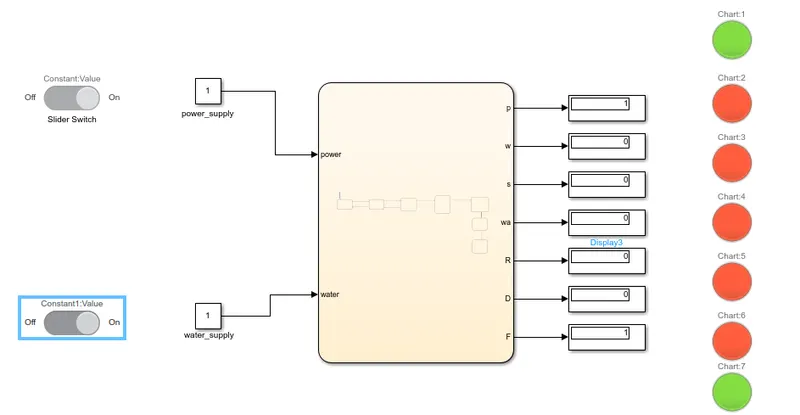
- Implement control logic of a “washing machine” using Stateflow as per given sequence:
- If the power supply is available, the system gets activated
- If the Water supply is not available, stop the process & indicate through LED
- Soaking time should be 200s followed by Washing time of 100s.
- Then rinsing happens for next 20s & dryer runs for 50s
After all the processes have completed turn on the finished LED
Simulink model of a Washing Machine.
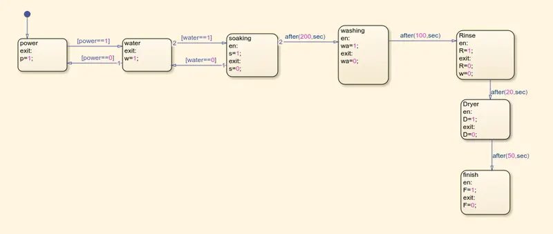
Logic inside the chart (Stateflow).
Explanation
- Starting by creating a stateflow chart containing all the process involved in Washing machine (ex.1.Power supply 2.Water supply 3.Soaking time 4. Washing time 5.Rinsing 6.Drying 7.Finish (end))
- The very first block is a Power supply block which should be on always to run the machine otherwise the machine will not start.
- Second block is Water supply block, Water is necessory to wash the clothes without which the purpose of the washing machine will not be fulfilled therfore the water supply should also be switched on to make the process work successfully.
- Third block is Soaking which will go on for a specified time and then the process will end and move on to the next process.
- The next process is washing will also go on for a specified time and then the process will stop and move on to the next.
- The same Procedure will be followed for the other two processes i.e Rinsing and Drying as well and finally the clothes are washed up rinsed and dried the process is complete and last block will be executed and will show a green light as shown in the stateflow diagram
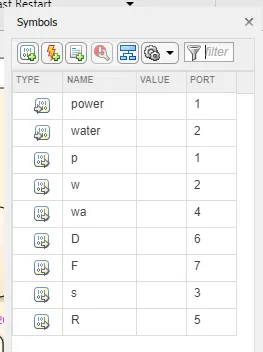
Symbols table.
Results
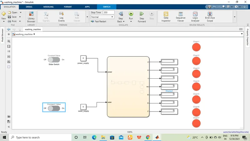
1. When both Power and water supply is switched off.
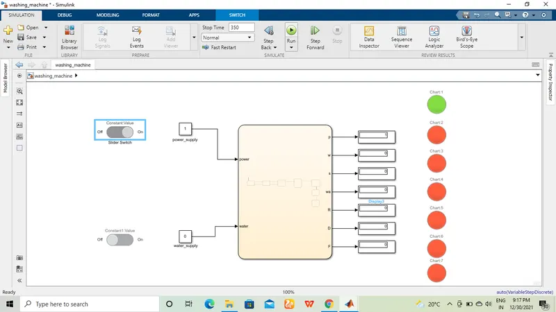
2.When only power supply is On and water supply is Off.
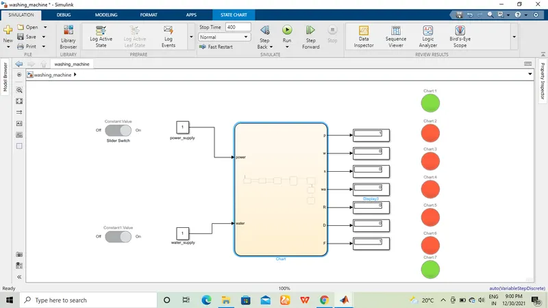
3.When both are On.
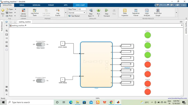
4. Both on but stop time is given as 100 seconds.
5. Both on but stop time is given as 300 seconds.
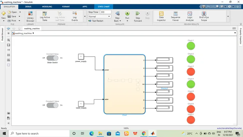
6. Both on but stop time is given as 350 seconds.
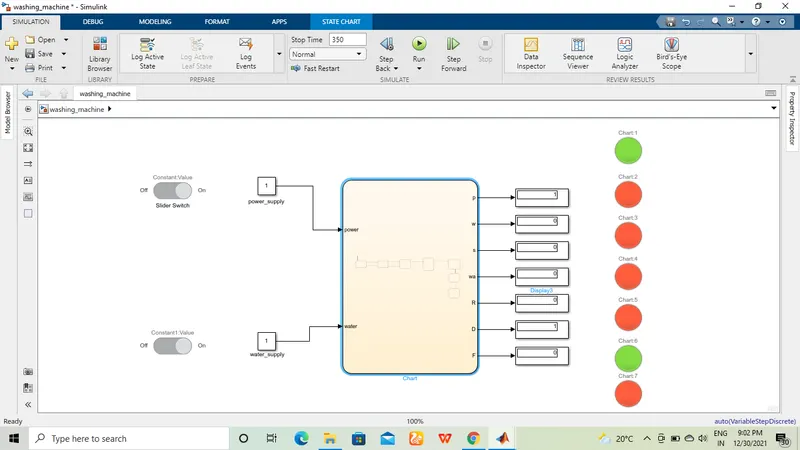
7. Both on but stop time is given as 400 seconds.
GEAR SHIFT
Aim
To make a Simulink chart for the “Gear shift” logic as per below conditions:
Speed Range(kmph) Gear
0 to 15 1
16 to 25 2
26 to 40 3
41 to 60 4
Above 61 5
Give speed input while the simulation is running & display the gear number.
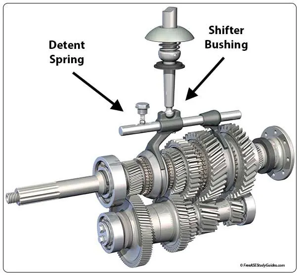
The picture below is a gear shifting arrangement of an Automobile.
Simulink model for Gear Shift
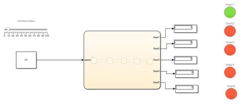
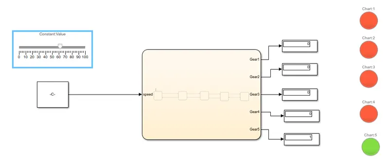
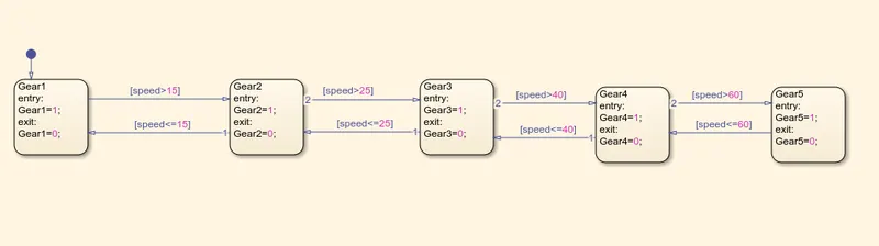
Stateflow chart
Blocks used
1. Constant block
2. Slider block
3. Chart
4. Display
5. Lamp
Explanation
- As per the instructions given in the question a stateflow chart is used to build the model of a gear shift mechanism.
- The first block of the chart conatians the logic for the gear1 which operates if the speed limit is does not exceed 15 (kmph).
- The second block contains the logic for the gear 2 which comes into action when speed limit crosses the 15 mark
- Similarly there are 3 more blocks for gear3, gear4 and gear5 which work on the same logic
- i.e when speed is more than 25(kmph) gear3 operates, when speed is more than gear4 operates and when speed is morer than 60 gear 5 operates.
Results
1. when speed is less than 15 kmph gear1 is operating.
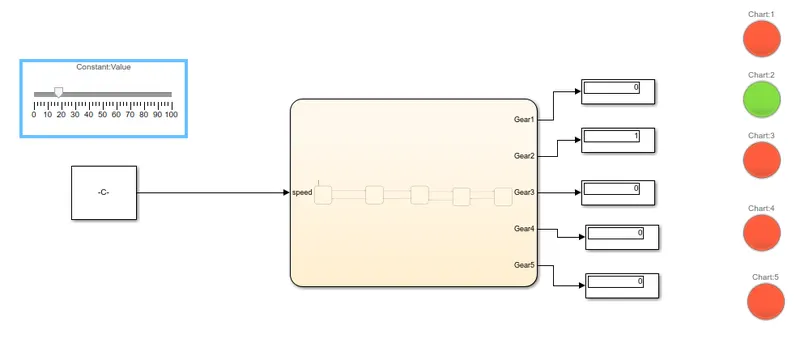
2. when speed is lies between than 16 and 25 kmph gear2 is operating.
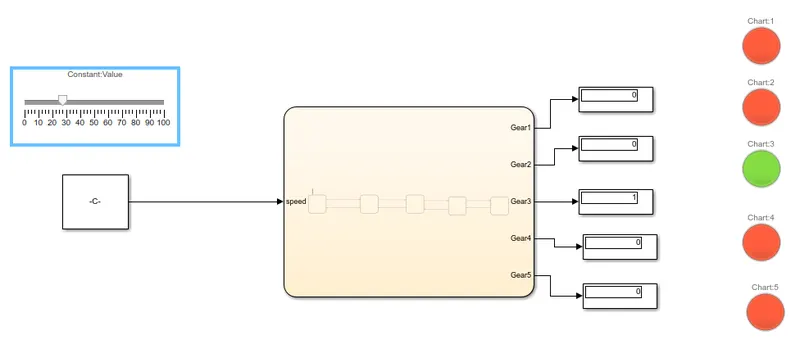
3. when speed is lies between than 26 and 40 kmph gear3 is operating.
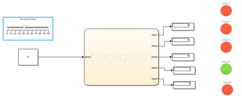
4. when speed is lies between than 41 and 60 kmph gear4 is operating.
5. when speed is above 61 kmph gear5 is operating.