Week - 4
Aim: To implement logic control of a 'Washing Machine' using Stateflow and to make the chart on Simulink for the 'Gearbox' logic.
#Case 1:
Conditions for the Washing Machine:
i) If the power supply is available, the system gets activated
ii) If the Water supply is not available, stop the process & indicate through LED
iii) Soaking time should be 200s followed by Washing time of 100s.
iv) Then rinsing happens for the next 20s & dryer runs for the 50s.
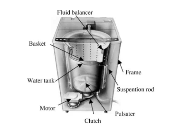
Washing Machine: It is a machine used to wash various types of clothes without applying any physical effort from the human end. The washing machine washes clothes automatically as the rotation of the drum takes place in both clockwise & anti-clockwise directions (centrifugal action) without having to supervise its operation. All we have to do is put the clothes in the machine and select the wash mode. The washing machine automatically takes in the amount of water and detergent required and it also automatically sets the timer for washing, rinsing and drying as per the selected mode and the number of clothes.
Cycle involved in washing as per the conditions given:
- The washing machine is connected with the power source as the system gets activated it asks for the water supply to be filled in with water in the water tank.
- The water level is set as per the user requirement to wash the clothes in the washing machine.
- If the water supply is not available, the process will stop.
- Once the water gets filled in the water tank, soak process will take 200 sec. In this process, the clothes soaking happens inside the water drum with detergent.
- After, 200 sec of soak, wash will happen for 100 sec as per the conditions given.
- After the wash, rinse will happen for 20 sec. In rinse process of the wash cycle repeats, just without detergent.
- Once the clothes get rinsed, drying of clothes will take place for 50 sec.
- As the cycle gets completed, the indicator lamp will glow on finished.
- The clothes are washed and ready to be removed out from the washing machine by the user.
Components in the model:
- Chart
- Lamp
- Switch
- Display
- Constant
Logic involved in preparing chart for 'Washing Machine' model:
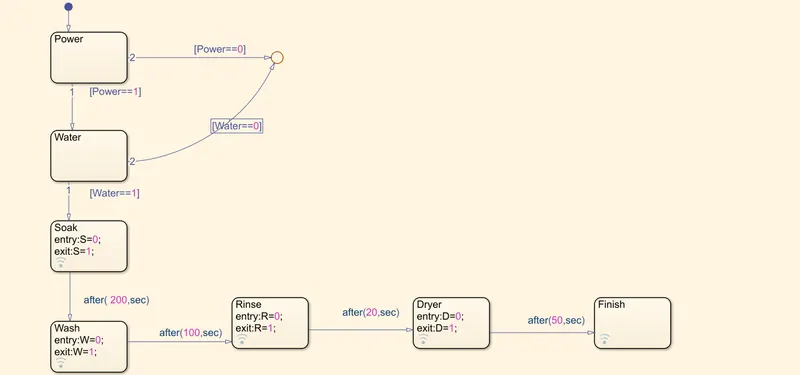
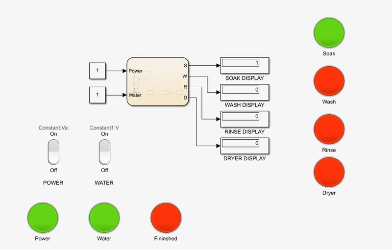
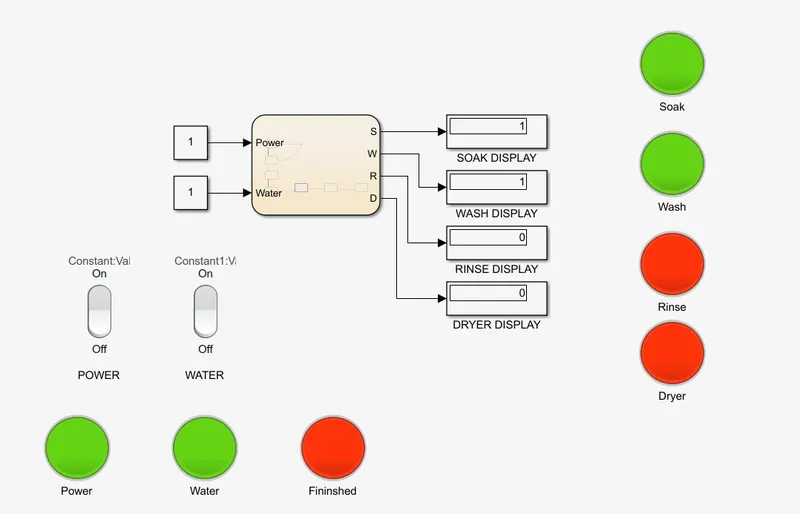
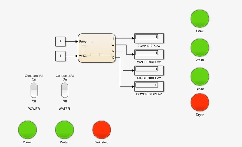
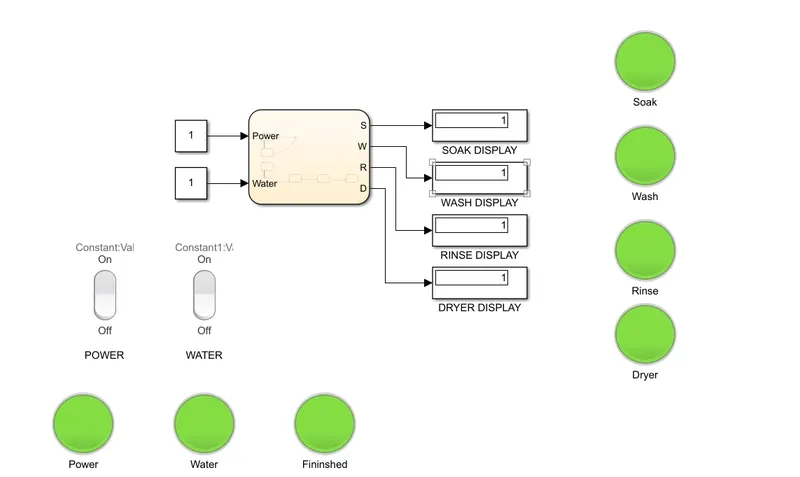
The logic is set as per the conditions provided and it is given within the chart. A chart is found in the Stateflow library, which we can use to implement the control logic. Once the logic gets implemented, the input and the output signals are connected with the chart. We have provided the power and water supply as input and the output can be monitored by the lamp signal.
- Condition results:
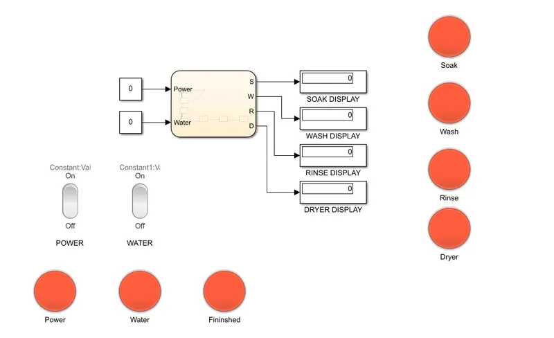
(i)Case: Power and Water supply OFF:-
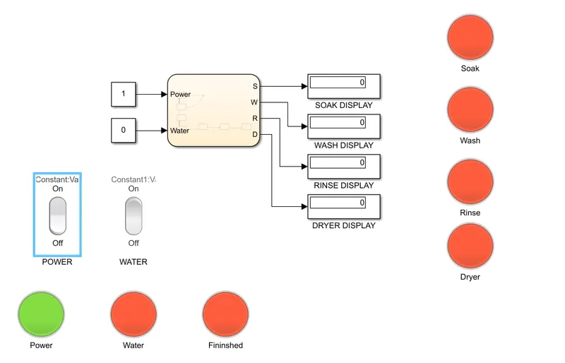
(ii)Case: Power ON and Water Supply OFF:-
(iii)Case: Power ON with Water Supply ON and Soak process completed:-
(iv)Case: Power On and Water supply ON, only Soak and Wash completed:-
(v)Case: Power On and Water supply ON, only Soak, Wash and Rinse completed:-
(vi)Case: Power On and Water supply ON, all process completed with Finished lamp indication:-
#Case 2:
Gearbox:
A gearbox is a mechanical device used to increase the output torque or to change the speed (RPM) of a motor. The shaft of the motor is connected to one end of the gearbox and through the internal configuration of gears of a gearbox, provides a given output torque and speed determined by the gear ratio.
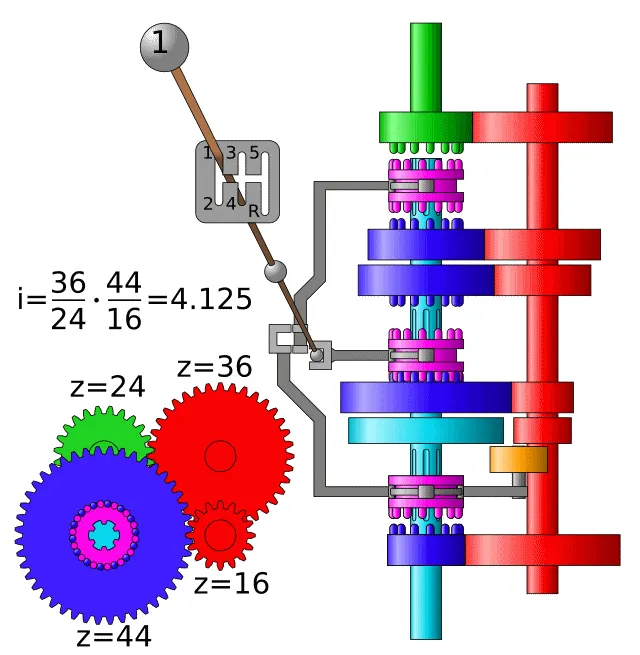
Given conditions:
Speed Range(kmph) Gear
0 to 15 1
16 to 25 2
26 to 40 3
41 to 60 4
Above 61 5
- Chart is prepared in the Stateflow and the logic is implemented as per the given conditions for gear-shift:
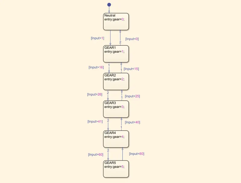
- The logic is implemented in the chart as per the speed conditions which are specified in each state. As the speed condition exceeds, the current state goes to the next state. Likewise for all the state/gears.
- Speed range=[1 2 3 4 5] gears are taken as output if the state satisfies the condition.
Components in the model are:
- Constant
- Slider gain
- Display
- Chart
- Lamp
Condition Results:
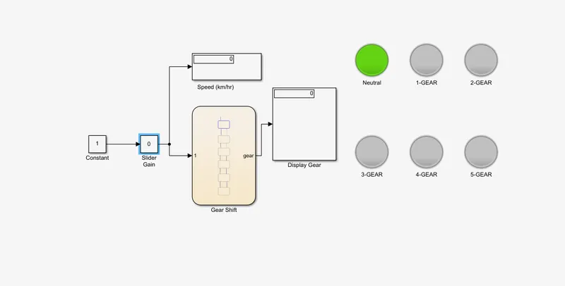
i) When the speed is 0 kmph:
The speed value as input is given to the slider gain block. We have added a lamp signal, here it is showing as neutral in the lamp signal.
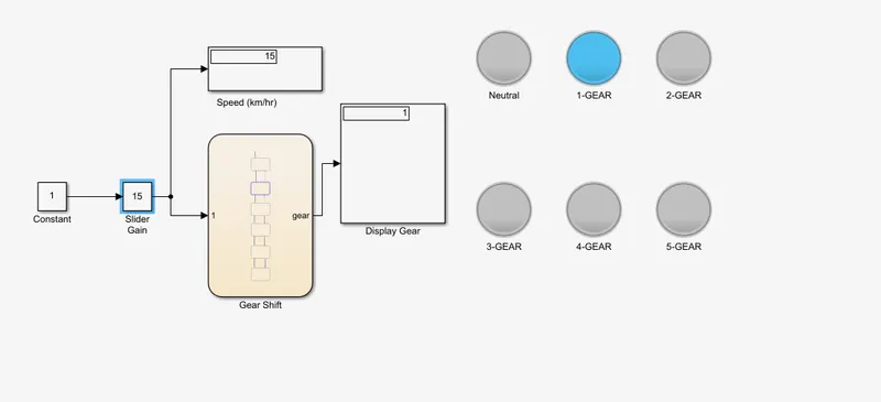
ii) At speed 15 kmph, the vehicle is in 1st-Gear:
iii) At speed of 25 kmph, the vehicle is showing 2nd-Gear indication:
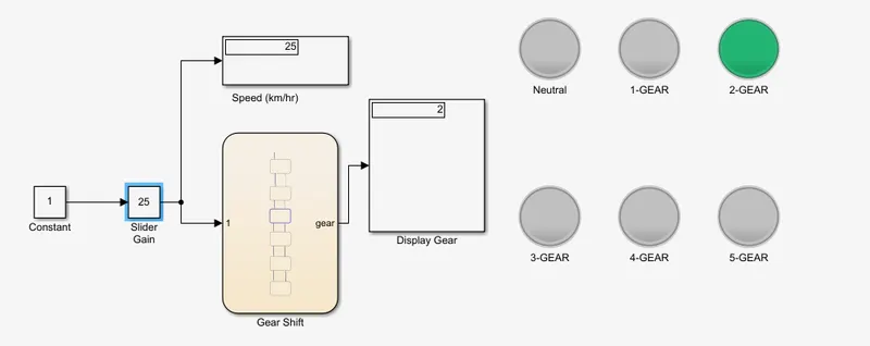
iv) At speed of 40 kmph, the vehicle is showing 3rd-Gear indication:
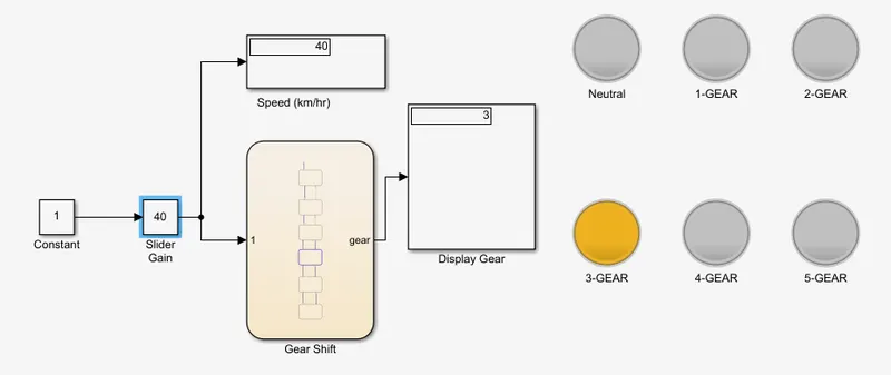
v) At speed of 60 kmph, the vehicle is showing 4th-Gear indication:
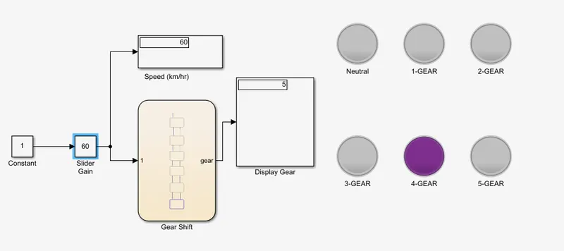
vi) At speed of 61 kmph, the vehicle is showing 5th-Gear indication:
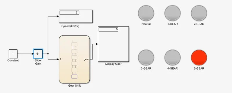
Conclusion:
By using Simulink, we are able to meet the conditions for the 'washing machine' and the results are shown after running the simulation. We have also achieved the results for the speed ranges in 'Gear-Shift' model with the indication of gears at different speed ranges.