Week -2
Aim: i) To make a Simulink model of Doorbell using solenoid block.
ii) To use the Thermister to sense the temperature of the heater and turn On or Off the fan.
i) Doorbell:
Objective: To create a situation where the switch is closed for 2 sec and then released also to observe the movement of the plunger.
Diagram for the doorbell
An electric doorbell is a simple circuit that triggers a sound on the completion of the circuit by pressing the button. The simple devices in the doorbell that works on the scientific principle of electromagnetism into action. In order to understand the operations of an electric bell, first, we need to understand 'what is an electromagnet'. In simple words, an electromagnet is basically a type of magnet in which the magnetic field is produced with the help of an electric current. Electrical influences in the electromagnet will result in works as a standard magnet (generating magnetic fields). When the power generation to an electromagnet stops, the production of the magnetic field also stops.
An electric source as we have used a battery to power the electromagnet used in an electric bell. The electric circuit is completed by installing a push switch which can be press to generate sound in an electric bell.
Simulink Blocks used in Doorbell model:
Pulse generator:
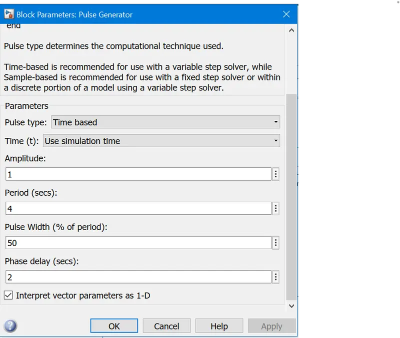
It is used to generate the pulse w.r.t time. Here, we have provided the input parameters as we know that the switch is closed for 2 sec and then released.
Scope:
It is used to display signal generated during the simulation.
Simulink-PS Converter:
It converts the simulink input signal to physical signal.
Switch:
A switch is used for the On/Off operation of the doorbell.
Battery:
A 12-V battery source is connected with the doorbell
Electrical Reference:
A model must have at least one electrical reference source(electrical ground).
Solenoid:
A solenoid block is used to function as an electromagnet for the doorbell model.
Ideal Translational Motion Sensor:
This block measures velocity or displacement in a mechanical translational network.
Mechanical reference:
A model must have at least one mechanical reference point i.e a frame or the ground.
PS-Siumlink Converter:
This block converts physical signals to simulink output signal.
Solver Configuration:
This block specifies the solver parameters that your model needs before you can begin simulation.
Display:
Display block shows the value of input data in the model.
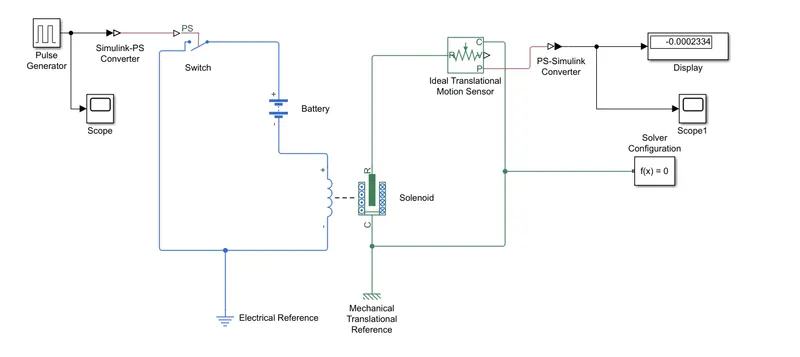
Block model for the Simulink Doorbell:
Input signal:
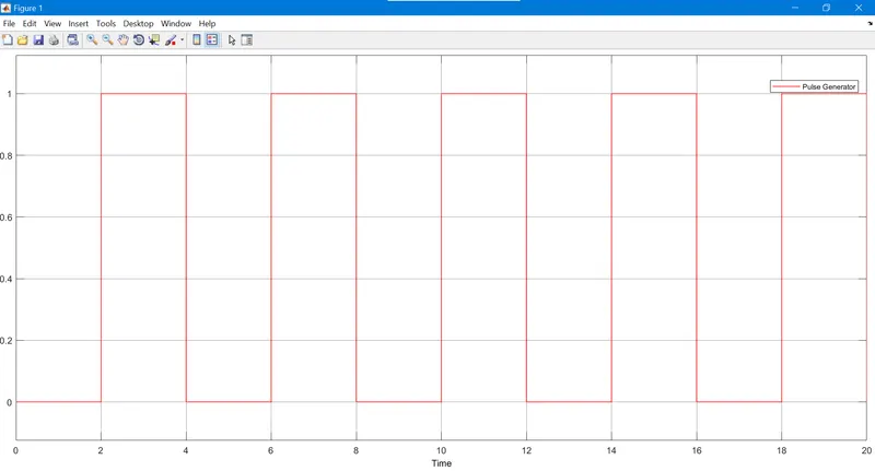
The input signal is given to pulse generator as shown in above figure.
Output Signal:
Conclusion for the doorbell:
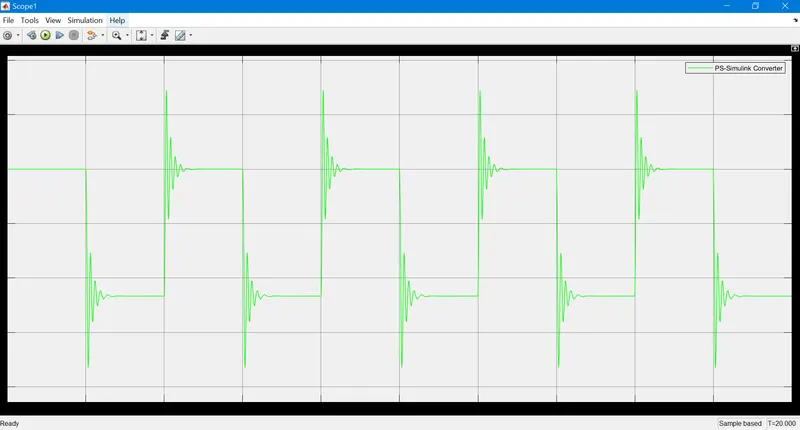
The input signal from the pulse generator is given as time period for 2 sec to open & close the circuit. When the switch is 'ON', current is supplied to the solenoid from the battery source. As the solenoid receives the current it gets excited and moves from 'R' to 'C' port to hit the bell and produce sound. Physical movement of the plunger is obtained by using translational motion sensor block and the physical output displayed to scope.
ii) Thermister:
Objective:
Temperature source: 20 °C from 0 to 10 seconds, 27 °C from 10 to 30 seconds, 23 °C from 30 to 50 seconds
Fan conditions: ON if the temperature above 25 °C, OFF otherwise.
As per the condition,
We have used signal builder to create input signal for the temperature ranges (in kelvin) as below:
i) from 0 to 10 seconds, temp. is 20 °C and in kelvin = 293
ii) from 10 to 30 seconds, temp. is 27 °C and in kelvin = 300
iii) from 30 to 50 seconds, temp. is 23 °C and in kelvin = 296
A thermister is a device which has resistance in accordance to the temperature. Its electrical resistance varies with the change in temperature or thermally sensitive resistor. There are two types of resisters which are used as-
i) NTC (Negative Temperature Coefficient) type:
This type of thermister decreases its resistance value with increase in the temperature. These are most widely used in the application of temperature measurement, temperature control
ii)PTC (Positive Temperature Coefficient) type:
In this type of thermister, resistance value increases with the increase in temperature. These are used in circuit protection and current limiting.
Some of the blocks which are used in creating a simulink fan model with the use of thermister are given below:
Signal builder:
It is used to here to add the input values for the given conditions of temperature w.r.t time.
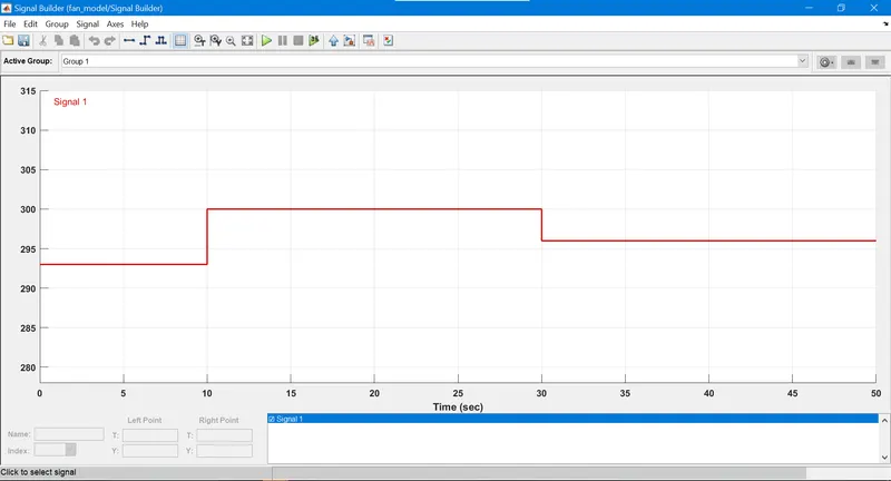
Fig. for signal builder
Controlled Temperature source:
This block represents an ideal energy source in a thermal network that can maintain a controlled temperature difference regardless of the heat flow rate. The temperature difference is set by the physical signal port S. A positive temperature difference causes the temperature at port B to be greater than the temperature at port A.
Thermister:
This type of resister whose resistance depend upon the temperature.
Resister:
A linear resistor is used for the model which also describes the relation as-
R= V/I
where,
V= voltage across the thermister, I= current passing through the thermister & R= resistance of the thermister
Voltage Senser:
Device that converts voltage measured between any electrical connections into a physical signal proportional to the voltage.
Battery:
A 12-V battery source is provided to the model based on the parameters given.
Switch:
It is used for the On/Off operation as the input signals are provided and as per the condition, if the value goes above the threshold limit then the application(Fan) to turn ON otherwise OFF.
Scope:
It is used to show the final result output.
Representation of block model on Simulink:
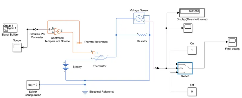
Terminology used in the model:
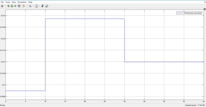
Creating the temperature conditions in Signal builder to the controlled temperature source as in connection with the thermister which sense the temp. of heater. As per the condition, Fan must on at the threshold value which is 25 °C or 298 kelvin so for that, we have connected a battery source also a linear resistor in series with thermister to xlaculate the resistance value. A voltage sensor in parallel with the resistor to calculate the voltage drop and that voltage drop is given as the input to the switch as threshold value (0.01099) to switch On the fan otherwise Off.
Threshold data graph
Fianl output:
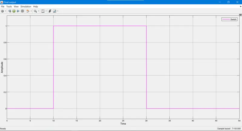
Conclusion:
Using simulink, we made the model which shows for the time 0 to 10 sec fan will remain 'OFF' as the temperature is 293 k which is below the threshold temp. 298k. From 10 to 30 sec the fan gets 'ON' as the temperature reaches 300 k greater than 298 k and from 30 to 50 sec the temperature is 296 k below the threshold temp. so the fab will be 'OFF'.