Week - 4
AIM:
Implement control logic of a “washing machine” using Stateflow as per given sequence:
- If the power supply is available, the system gets activated.
- If the Water supply is not available, stop the process & indicate through the LED.
- Soaking time should be 200s followed by Washing time of 100s.
- Then rinsing happens for the next 20s & dryer runs for 50s.
Theory:
- The main principles behind the working of a washing machine are the centrifugal and centripetal forces, Where centrifugation helps quicken the process of sedimentation of different density particles to clean the laundry in the washing machine.
- The washing machine operates in two primary cycles. These are the wash cycle and the rinse cycle.
- The wash cycle involves the principle of centrifugal force. This force’s direction is from inside to outside, ensuring that every part of the cloth is rinsed adequately in the soap water mixed in the machine.
- The rinse cycle involves the principle of centripetal force. This force acts from outside to inside and creates a vacuum-like space in the middle of the washing machine.
- These two cycles work one after another several times, and as a result, the entire cleaning process occurs.
Step by step mechanism of the working of washing machine:
- Firstly before the washing machine starts to operate, you need to get it ready for the washing. Getting the machine ready includes filling the washing machine with water held in the outer drum and stopping the water from leaking while operating. Then you put the clothes inside the inner drum.
- The inner drum is the drum on which the different forces give you a cleaner version of your clothes. Then you put the detergent into the machine, and after plugging in the device, we are ready to go.
- There is a thermostat present inside the washing machine. After turning on the device, the thermostat measures the temperature and increases the heat according to its need. When the water is hot enough for operation, the inner drum rotates back and forth on time, mixing the cloth properly with the soap water.
- Now the work of the detergent begins. We have all studied how soaps and detergents work, and due to the motion of the particles, detergents can do their job correctly and scrub off all the dirt molecules from the clothes.
- In the next step, if one uses a fully automatic washing machine, the machine opens the valves and lets the dirty water flow away. Then, the programmer opens the valves again to allow clean water to come into the drum.
- After the clean water comes in, the inner drum starts to rotate to rinse the clothes properly. This rinsing process, removing the dirty water, taking new water, and rinsing again is repeated several times to improve efficiency.
- After the clothes’ proper rinsing, the machine starts to rotate the inner drum vigorously at high speed of around 130 km/h. these force is from the inside to outside and flung the clothes from the inner edge to the drum’s outer edge.
- This final churning allows the proper cleaning of clothes, and after this step, the remaining water is let out from the valve, and you get your set of clean clothes.
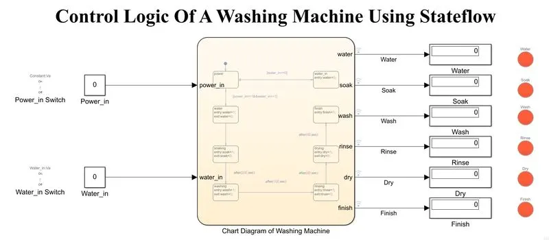
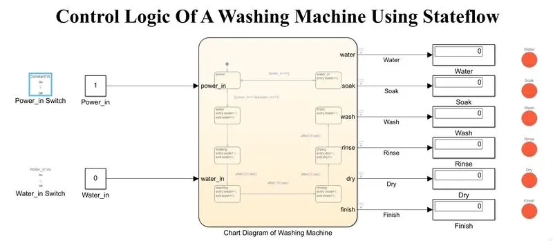
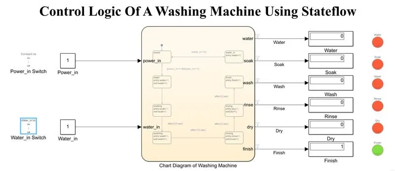
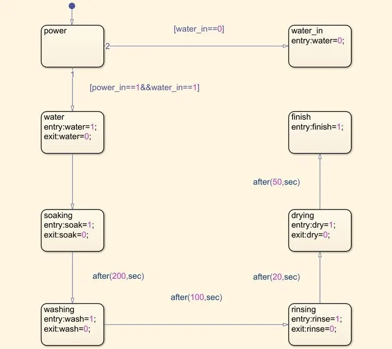
- First, create the chart diagram with all the parameters. It is used to define the washing machine state flow process.
- Next, create the symbols, which are inputs and outputs.
- Next, create the constants and connect them to the toggle switch to supply power and water.
- Next, create the displays and connect them to the outputs of the charts so that they will show the change in the Stateflow.
- Next, show the change in the displays through lamps, red means not working, and green means work completed.
-
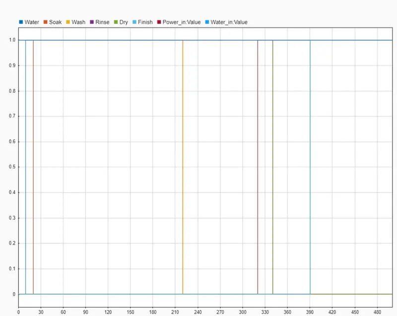
When the power and water supply value is '1,' the process begins and the soaking process will be done up to 200 secs.
-
After 200 secs the soaking will be stopped, and the washing process will be done for the next 100 secs.
-
After the time value of 300 secs, the next rinsing process will be started and completed after 20 secs, i.e., after 320 secs.
-
Finally, the drying process will be for 70 secs, and after 370 secs, the washing of the machine will be stopped automatically.
AIM:
Make a Simulink chart for the “Gear shift” logic as per below conditions:
Speed Range(kmph) Gear
0 to 15 1
16 to 25 2
26 to 40 3
41 to 60 4
Above 61 5
Theory:
- A car transmission, also known as the transmission system, is the mechanism by which power created by the engine is transferred to the driving wheels. This part of the vehicle is the most important in determining the power and functionality of your engine systems.
- A transmission is a machine in a power transmission system that provides controlled power application. Often the term 5-speed transmission refers simply to the gearbox that uses gears and gear trains to provide speed and torque block conversions from a rotating power source to another device.
- The term transmission properly refers to the whole drivetrain, including clutch, gearbox, prop shaft (for rear-wheel drive vehicles), differential, and final drive shafts. In America, the term is sometimes used in casual speech to refer more specifically to the gearbox alone, and detailed usage differs.
- The most common use is in motor vehicles, where the transmission adapts the output of the internal combustion engine to the drive wheels. Such engines need to operate at a relatively high rotational speed, which is inappropriate for starting, stopping, and slower travel. The transmission reduces the higher engine speed to the slower wheel speed, increasing torque in the process. Transmissions are also used on pedal bicycles, fixed machines, and where different rotational speeds and torques are adapted.
- Often, a transmission has multiple gear ratios (or simply "gears") with the ability to switch between them as the speed varies. This switching may be done manually (by the operator) or automatically (by a control unit). Directional (forward and reverse) control may also be provided. Single-ratio transmissions also exist, which simply change motor output's speed and torque (and sometimes direction).
- In motor vehicles, the transmission is generally connected to the engine crankshaft via a flywheel, clutch, or fluid coupling, partly because internal combustion engines cannot run below a particular speed. The transmission output is transmitted via the driveshaft to one or more differentials, which drive the wheels. While a differential may also provide gear reduction, its primary purpose is to permit the wheels at either end of an axle to rotate at different speeds (essential to avoid wheel slippage on turns) as it changes the direction of rotation.
- Conventional gear/belt transmissions are not the only speed/torque adaptation mechanism. Alternative mechanisms include torque converters and power transformation (e.g., diesel-electric transmission and hydraulic drive system). Hybrid configurations also exist. Automatic transmissions use a valve body to shift gears using fluid pressures in response to engine RPM, speed, and throttle input.
Simulink Block Diagrams Of Gear Shift:
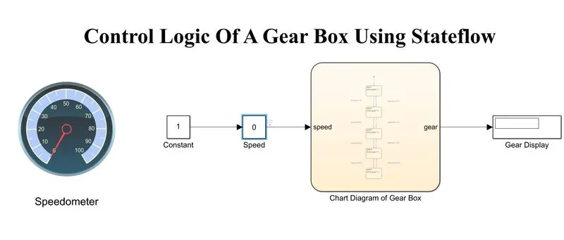
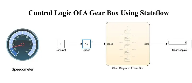
When speed = 15:
When speed = 25:
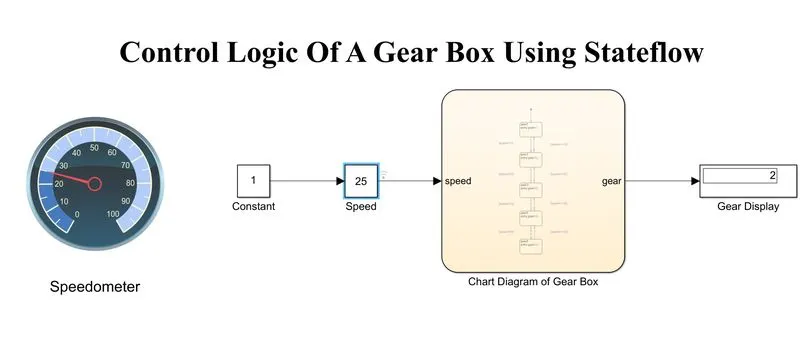
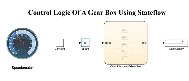
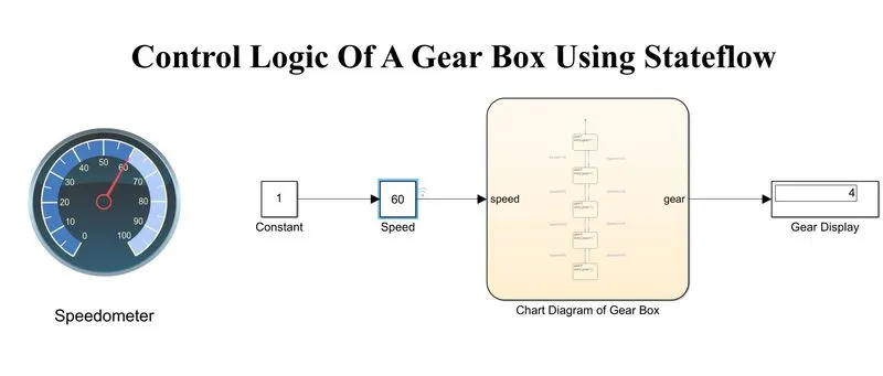
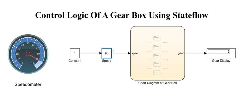
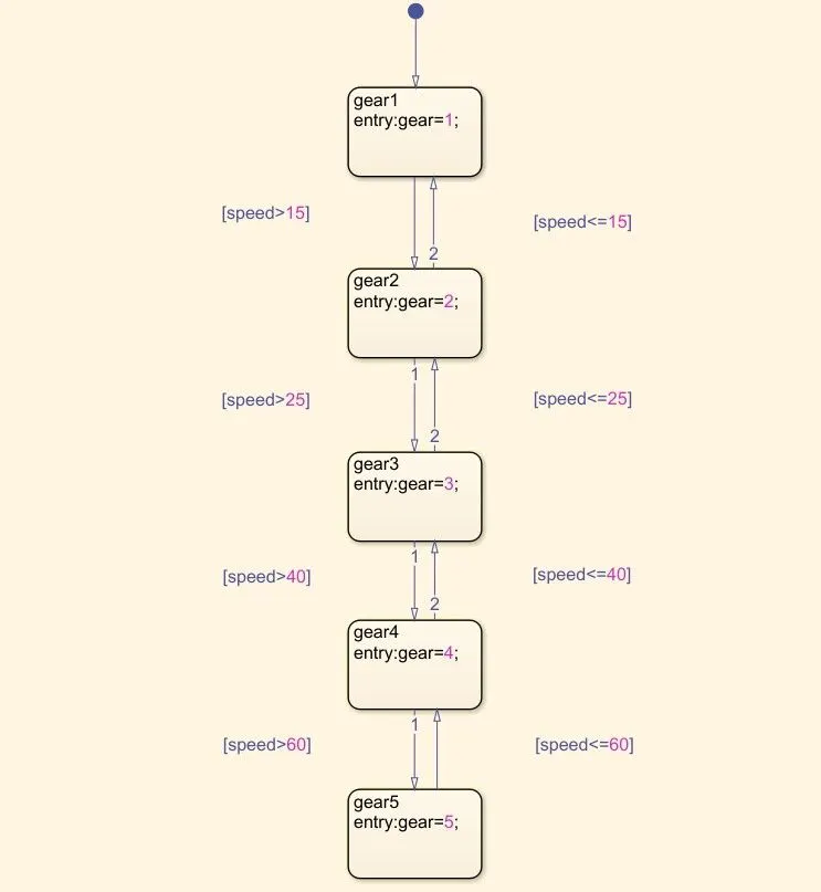
- First, create the chart diagram with all the parameters. It is used to define the Gear Shift state flow process.
- Next, create the symbols, which are inputs and outputs.
- Next, use the gain block to set the speed of the vehicle. And connect that to a constant and a gauge to show the speed.
- Next, connect the output of the chart to a display to show the vehicle's gear.
Links to the modules:
https://drive.google.com/file/d/1mvmG3OolOE_XtZ9aYuhcnSQn_9BeIMsH/view?usp=sharing
https://drive.google.com/file/d/1xOVLynps6A21jdbMRGwuvXtxHytWqtvX/view?usp=sharing