Week - 4
1. control logic of a “washing machine”
AIM & OBJECTIVE-
To implement control logic for a washing machine using Stateflow in Simulink
logic conditions
- If the power supply is available, the system gets activated
- If the Water supply is not available, stop the process & indicate through LED
- Soaking time should be 200s followed by Washing time of 100s.
- Then rinsing happens for the next 20s & dryer runs for 50s
Theory-
To implement the above control logic in state flow to perform the above sequences we need sub-blocks named state, junction, default transition, transition.
state block - this block is used to define a state and here the state name is defined and according to the state the action also is defined at that state.
transition - transition is a connection that is connected between two junctions or states and while going through the transition we can define conditions and actions that need to perform during the transition.
junction - it is a point used when a condition like if occurs then there will be two paths divided or joined at junction
procedure-
A washing machine is switched on and then the water supply is checked if there is no water supply then there is a bulb that glows into the red to indicate no water supply. if there is a water supply then it goes into the next state socking which is for 200 seconds and then washing for 100 seconds further rinsing for 20 seconds finally drying for 50 seconds to complete a wash cycle of cloths.
the above logic is implemented using the below state flow diagram
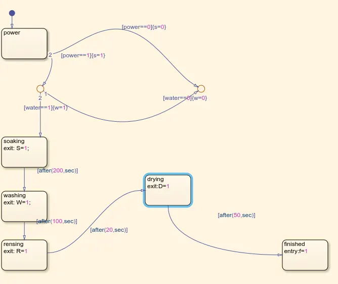
here S = socking, W=washing, R=rinsing, D= drying
and w = water supply indication, s= power supply indication,f= completion of the wash cycle.
let observe each case
case-1 (water supply given, power supply given)
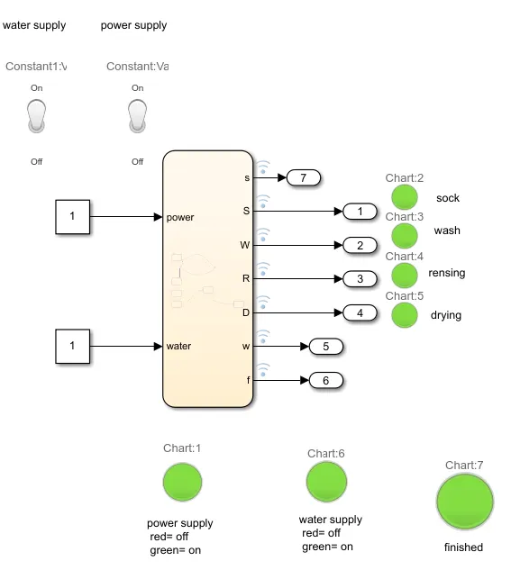
we can see all LED are green such that all operations performed well and the wash cycle is completed.
case-2(power supply on, water supply is not given)
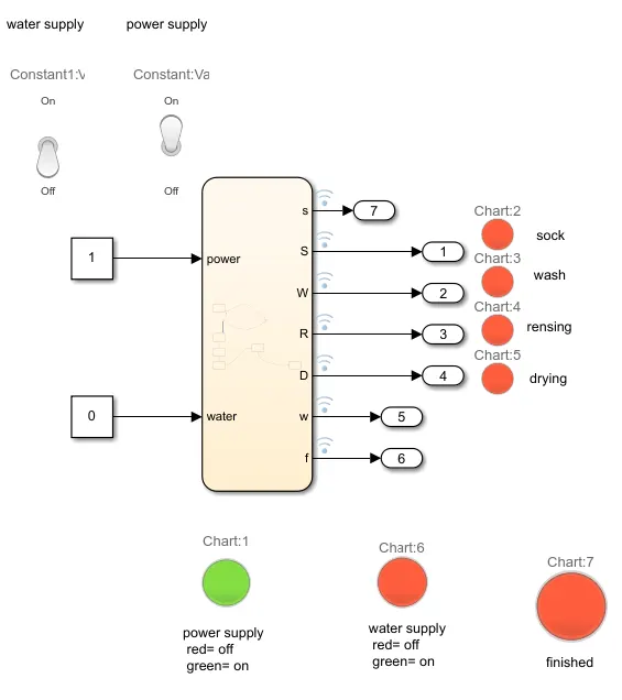
once the power supply is not given we can see there is a red indicator at the water supply and no further process is done.
case-3 (power supply off )
when the power supply is off regardless of water supply there is no action taken place
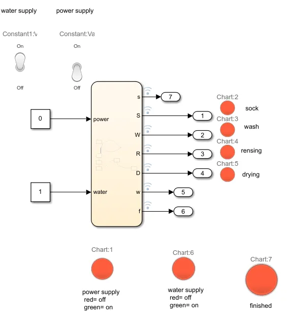
conclusion - the above actions are performed sequentially and further washing machine control logic is implemented in Simulink successfully.
2. Make a Simulink chart for the “Gear shift” logic
AIM & OBJECTIVE -
To implement the automatic gear selector according to speed using state flow in Simulink
logic conditions
Speed Range(kmph) Gear
0 to 15 1
16 to 25 2
26 to 40 3
41 to 60 4
Above 61 5
Procedure-
To implement the above logic same blocks which are used for the above example named state block, default transition, junction, transition are required.
the logic is implemented as below diagram in the state flow
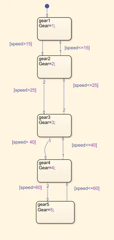
let observe the different cases
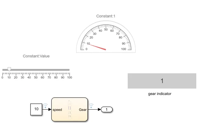
case-1 (speed is 10 km/hr i.e, below 15 km/hr gear should be 1)
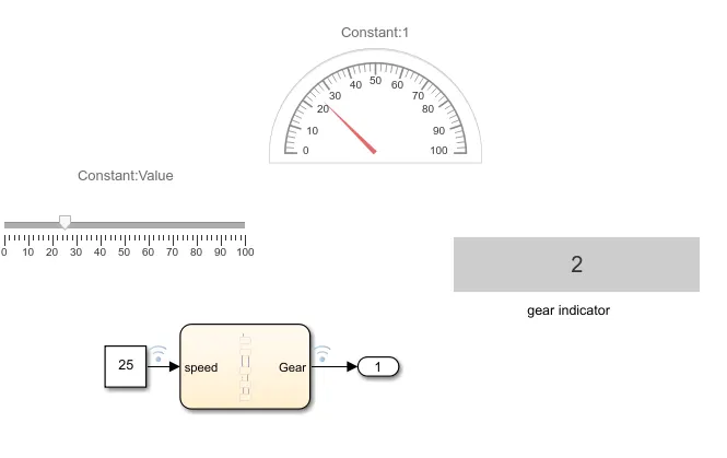
case-2 (speed is 20 km/hr i.e, below 25 km/hr gear should be 2)
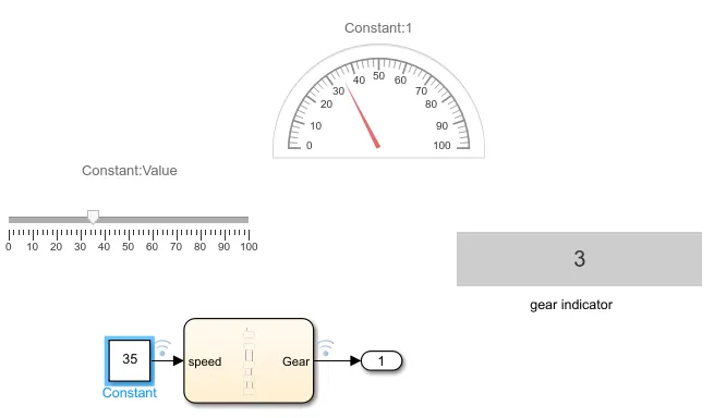
case-3 (speed is 35 km/hr i.e, below 40 km/hr gear should be 3)
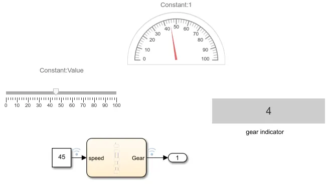
case-4 (speed is 45 km/hr i.e, below 60 km/hr gear should be 4)
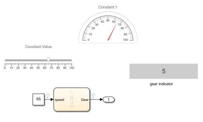
case-5 (speed is 65 km/hr i.e, above60 km/hr gear should be 5)
 \
\
conclusion - The above logic is implemented to shift the gear according to speed.