Week - 4
AIM:
To implement control logic of a washing machine using State flow and make a Simulink chart for the gear shift.
OBJECTIVES:
- To simulate the working of washing machine using state flow as per given sequence
- If the power supply is available, the system gets activated.
- If the water supply is available, stop the process and indicate through LED.
- Soaking time should be 200sec followed by washing time of 100sec.
- Then rinsing happens for next 20 sec and dryer runs for 50 sec.
- To make Simulink chart for gear shift as per given condition giving its speed input while the simulation is running and display the gear number.
The conditions:
|
Speed range(kmph) |
0 to 15 |
16 to 25 |
26 to 40 |
41 to 60 |
Above 61 |
|
Gear |
1 |
2 |
3 |
4 |
5 |
1) Washing Machine:
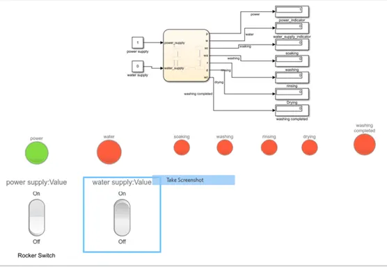
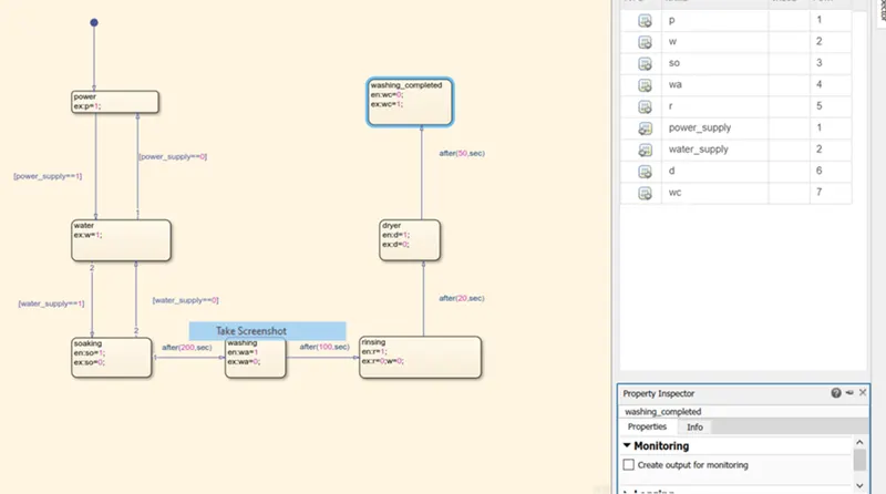
The block diagram and flow chart for the working of washing machine using state flow is shown below:
INPUT BLOCK:
1) Constant: The power supply and water supply is turned on and off by the input constant.
2) Rocket switch: The rocket switches are linked to the respective constant. The switch toggles between 1 and 0. Denoting 0 as off and 1 as on.
OUTPUT BLOCK:
1) Display: The display block displays the output from each variables representing the process.
2) Lamp: The 7 lamp block are linked to the respective display. The lamp turns green when input signal is 1 and turns red when input is 0.
PROCESS:
From this block diagram process is shown in the below:

Step-1: Power supply (p=1) is turned ON, the power supply LED turns to green color.
Step-2: water supply (w=1) is turned ON, the water supply LED turns to green color.
Step-3: soaking is done for 200 sec is set by the condition after(200,sec) , the soaking indicator (so=1) turns from red to green color and turn back to red after 200 sec.
Step-4: washing is done for 100 sec is set by the condition after(100,sec), the washing indicator (wa=1) turns from red to green color and turns back red after 100sec.
Step-5: rinsing is done for 20 sec is set by the condition after(20,sec), the rinsing indicator (r=1) turns from red to green color and turns to red after 20 sec.
Step-6: The water supply (w=0) is turned OFF as rinsing is done. The water supply indicator is turned red.
Step-7: The dryer process is done for 50 sec is set by the condition after(50,sec), the dryer indicator (d=1) is turned from red to green color and turns to red after 50 sec.
Step-8: The washing completed indicator (wc=1) turns to green at the end of 50 sec for dryer.
OUTPUT:
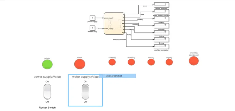
Here are result for the given conditions:
1) POWER IS ACTIVATED:
2) WATER SUPPLY IS ACTIVATED:
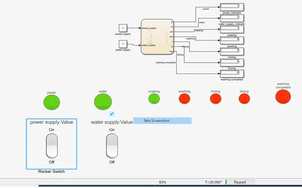
3) SOAKING, WASHING, RINSING AND DRYING:
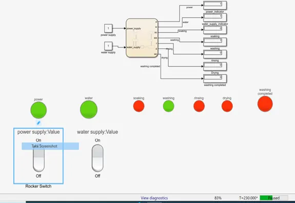
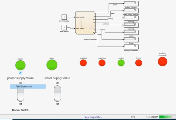
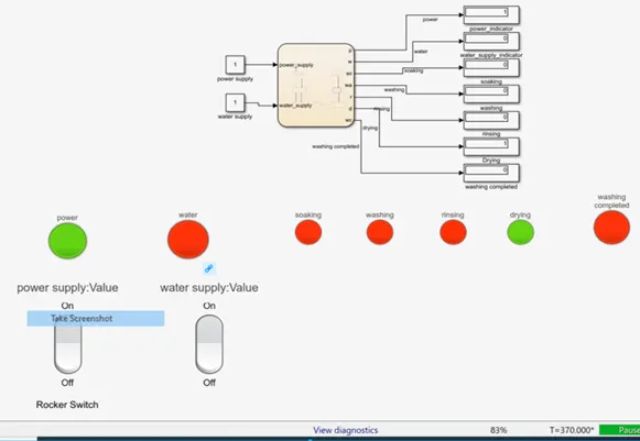
2) GEAR SHIFTING INDICATOR:
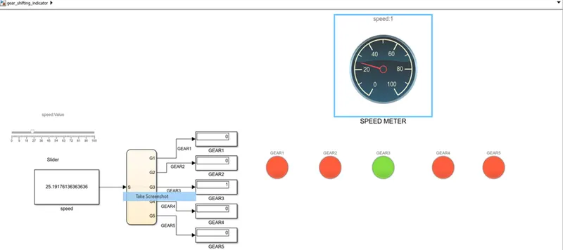
The block diagram and flow chart for the working of Gear shifting indicator using state flow is shown below:

INPUT BLOCK:
Constant: The speed is taken as the input. The constant block is linked to slider block.
Slider: the slider block is the block which can vary the input parameter value with sliding scale.
OUTPUT BLOCK:
Display: The display block displays the output from each variables representing the process.
Lamp: The 5 lamp block are linked to the respective display. The lamp turns green when input signal is 1 and turns red when input is 0.
PROCESS:
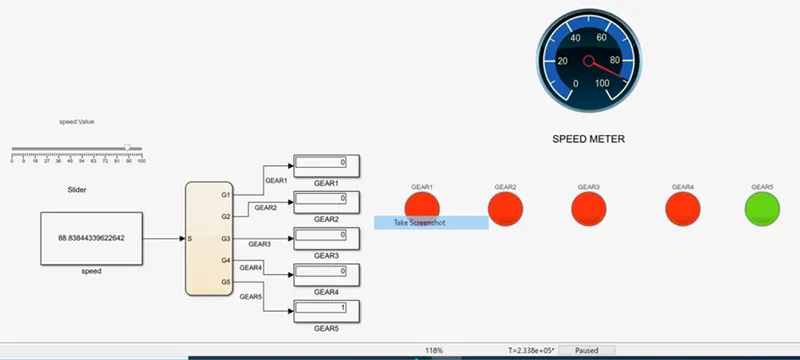
The flow chat uses if condition, where the input speed is compared with the conditions and the values of the variables G1, G2, G3, G4 and G5 varies from 0 and 1.
From this block diagram process is shown in the below: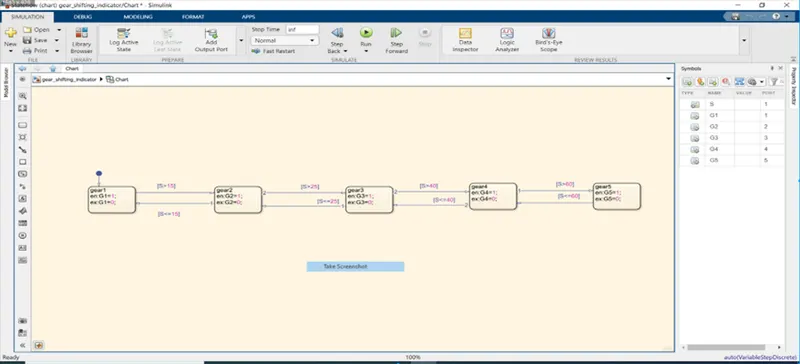
OUTPUT:
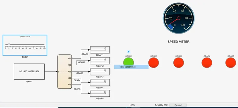
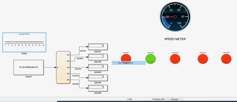
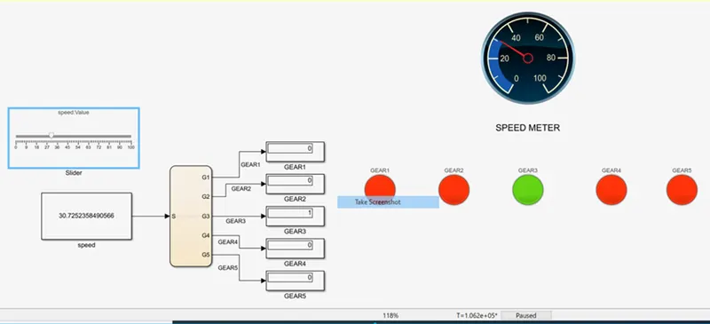
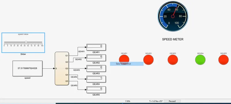
The following image shows the speed in the speed meter and indicator turns from red to green color with respect to varying speed.