Week -2
AIM:
To make a Simulink model of Doorbell and a thermistor controlled Fan.
OBJECTIVES:
- Make a Simulink model of Doorbell using Solenoid block and observe the position and velocity of the plunger when Switch is closed for 2 seconds and then released.
- Use a thermistor to sense the temperature of a heater & turn on or turn off the fan as per the below conditions:
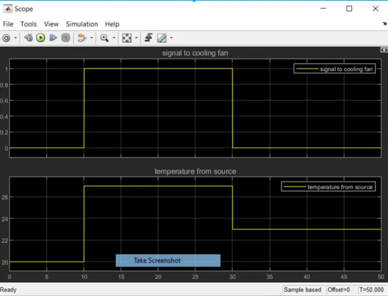
- Temperature source: 20 °C from 0 to 10 seconds, 27 °C from 10 to 30 seconds, 23 °C from 30 to 50 seconds
- Fan conditions: ON if the temperature above 25 °C, OFF otherwise
- DOORBELL :
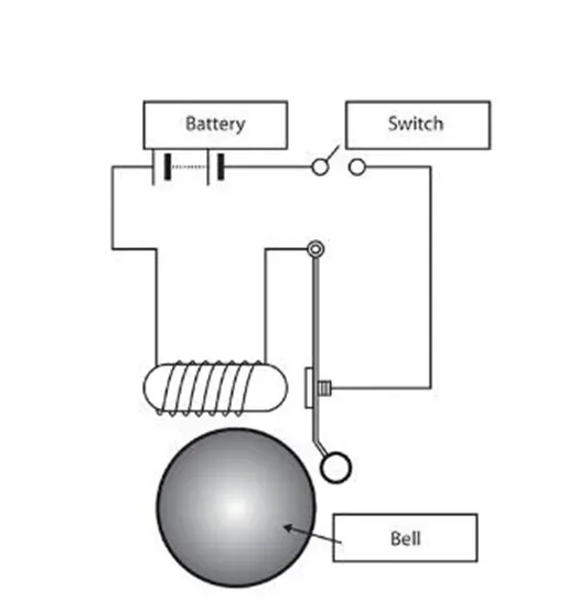
The following diagram is arrangement of the doorbell.
SIMULINK MODEL:
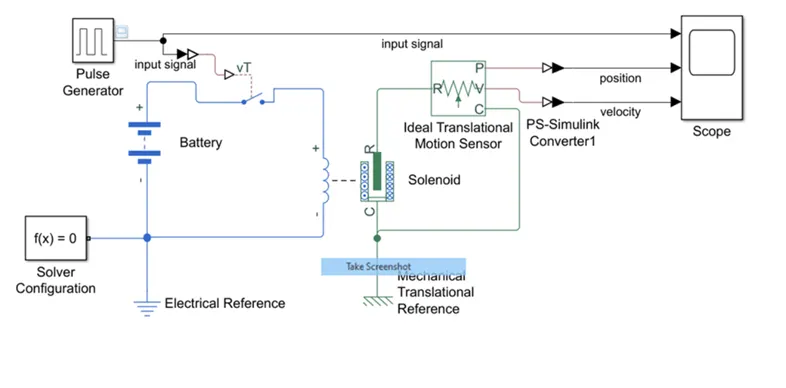
The block are arrange as shown in the figure below.
BLOCKS USED:
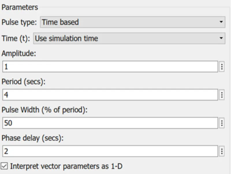
- PULSED GENERATOR: The Pulse Generatorblock generates square wave pulses at regular intervals. The parameters are set as shown below.
- SIMULINK-PS CONVERTER AND PS-SIMULINK CONVERTER: The Simulink-PS converter converts Simulinkinput signal into physical signal. The Simulink-PS converter converts physical signal into Simulink input signal.
- SPDT SWITCH: single-pole single-throw switch. The switch is turned ON and OFF by the input signal from the pulsed generator. When input signal is more than the threshold value 0.5V the switch turns ON below 0.5V the switch turns OFF.
- BATTERY: The Batteryblock represents a simple battery model. A default parameters are set to the battery block.
- SOLENOID: the solenoid block represent a solenoid actuator. The solenoid is an electromechanical device comprises of coil of wire and movable plunger. When electric current is introduced a magnetic field is produced in the coil which moves plunger in linear direction as the power is turned ON and OFF. The default parameters is set to the solenoid block.
- IDEAL TRANSLATIONAL MOTION SENSOR: This block senses the translational movement of the plunger in the solenoid and show the plunger velocity and position as the output.
- SIMSCAPE REFERENCES: In this model two reference are used one is electrical reference and another one is mechanical reference.
- SCOPE: the scope block display signals generated during simulation. The motion of the plunger is shown below with respect to time.
OUTPUT:
In the following picture input signal, velocity of plunger and position of the plunger are plotted. From this plot we could observe that the input signal is turned ON and OFF after every 2 sec. Thus the switch is turned ON and OFF after every 2 sec.
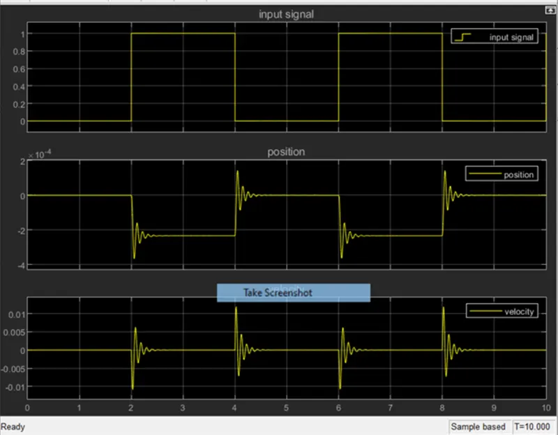
The position and velocity of the plunger changes with respect to the input signal which represent the displacement of the plunger in the solenoid. The plunger moves due to the electromagnetic signals from the input signal which varies every 2 sec. Thus the movement of the plunger is observed.
- THERMISTER FAN CONTROLLER :
SIMULINK MODEL:
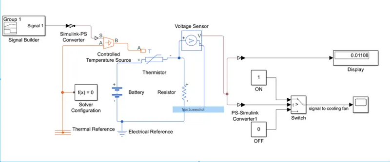
The following Simulink block diagram is required block diagram to control the fan.
INPUT:
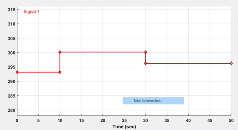
Since the thermal source temperature is given in the question, Signal builder block is used to achieve the following conditions:
- 20 °C(293.15K) from 0 to 10 seconds
- 27 °C(300.15K) from 10 to 30 seconds
- 23 °C(296.15K) from 30 to 50 seconds
The temperature is plotted in kelvin. The plot is shown below.
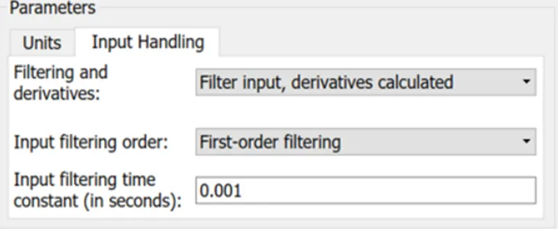
SIMULINK-PS CONVERTER: Convert Simulink input signal into physical signal. The parameter filter and derivatives are to be changed to Filter input, derivatives calculated as shown below. Since signal builder can is not same as constant block error occur at the output while using default parameter.
PROCESS:
- The plotted signal from the signal builder block is sent to PS-Simulink converter.
- The Simulink-PS converter converts the signal and fed it to the input of the controlled temperature source.
- The controlled temperature source is connected in series with a battery as source of current and a resistor as load. A voltage sensor is connected parallel to the load. The output from the voltage sensor consist of signal in phase similar to temperature input.
- The output from the voltage sensor is converted to Simulink readable signal with the help of PS-Simulink converter.
- The switch bock in the Simulink act as if else condition block. A threshold value is set as 0.01196 which is equal to 25 °C (found with respect to input signal).
- Two constant block are used. One with value 1 and another with 0. The Fan turn ON when the signal turns 1 and OFF when the signal is turned to 0.
- By this switch the fan is turned ON when the temperature is above 25°C and OFF when temperature is below 25°C.
- The temperature sensor is connected between A and B of the controlled thermal source and converted to Celsius to compare at scope.
OUTPUT:
The signal from the switch is plotted in scope shown below. This signal is turn ON at 10 sec and turn OFF at 30 sec. Thus result is achieved.