Week - 4
- Implement control logic of a “washing machine” using Stateflow as per given sequence:
- If the power supply is available, the system gets activated
- If the Water supply is not available, stop the process & indicate through LED
- Soaking time should be 200s followed by Washing time of 100s.
- Then rinsing happens for the next 20s & dryer runs for 50s
After all the processes have been completed turn on the finished LED
- Make a Simulink chart for the “Gear shift” logic as per the below conditions:
Speed Range(kmph) Gear
0 to 15 1
16 to 25 2
26 to 40 3
41 to 60 4
Above 61 5
Give speed input while the simulation is running & display the gear number.
PROCEDURE
- For the run the above situation we need to create a Stateflow chart to perform the operation with respect to time.
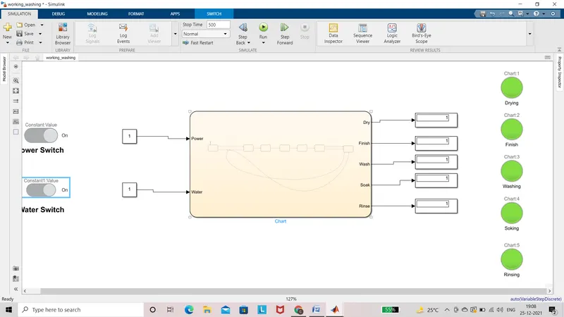
- As per the above situation, if the power supply Is available, the system gets activated. To start the machine we need to provide the input signal using a constant block. 1 signal indicates the ‘ON’ STATE, 0 signal indicates the ‘OFF’ STATE.
- if the power supply is on the input signal is directly goes to the output and glows the lamp. That indicates the power supply is on.
- switching the water switch is on the next system in Stateflow and then the next process is going on.
- each state shows a separate lamp.
6. here the two constant blocks are used one is used for power supply and another is used for water supply ‘1’ signal is used for ‘ON’ condition and ‘0’ is used for ‘OFF’. The lamp indicates the specific operation
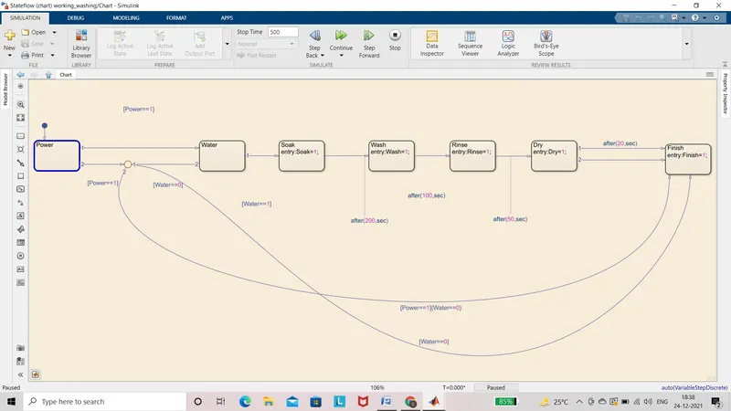
RESULT 1:
Simulink model are created and inputs are generated for power supply and water supply.
if power supply and water supply are assigned as ‘0’ value at that time all the operation will the off.
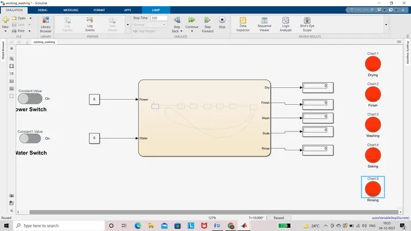
- In this state power supply, the state is available and the water supply state is ‘0’ showing the below result. The power is generated and that is indicated in display and the power lamp is glowing. Water supply is not available so that signal does not go further because of that all the next process is ‘OFF’
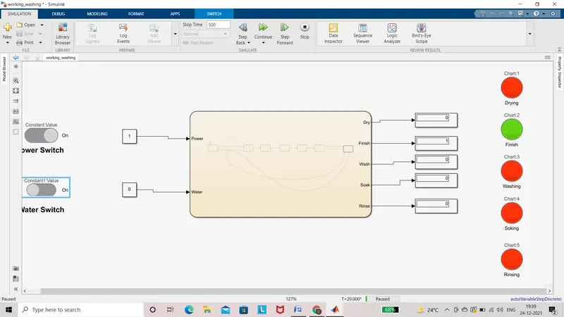
- Now the both power supply and water supply assigned as ‘1’ power are generated from input and operation is start. Water supply is also available so that is proceed the next operation and the indicate the LED
STUDY 2:GEAR SHIFTING
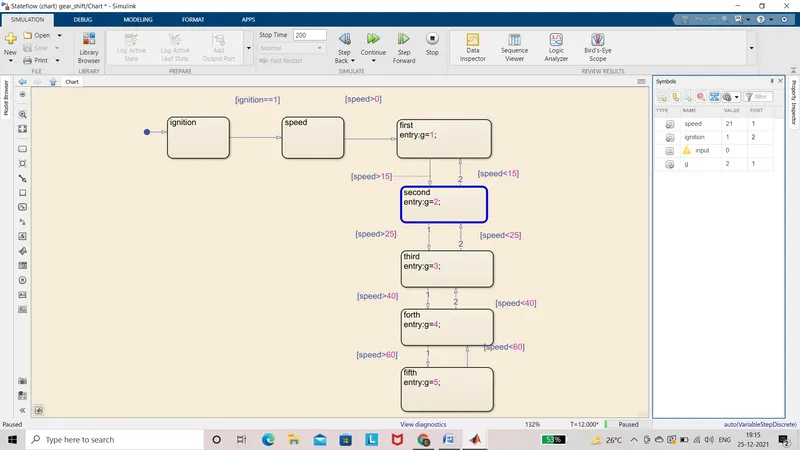
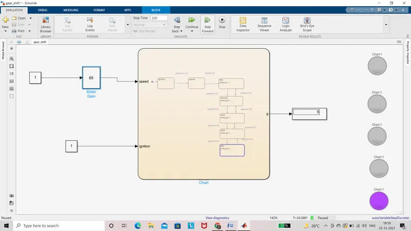
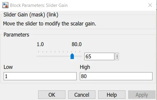
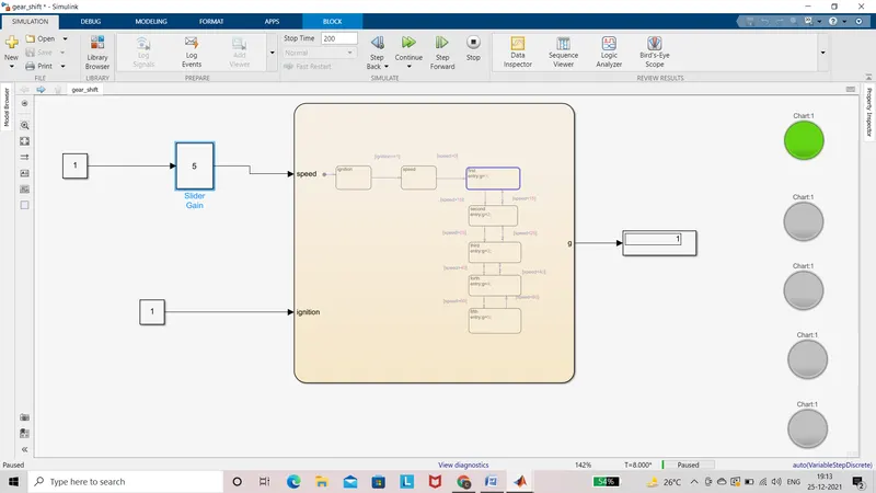
In this model, input is generated by using slider gain. The constant block is used to give the supply of slider gain. In the chart, the Stateflow is made as we required the gear shifting speed. Display block is used for indicating which gear is shifted
Neutral condition:-
When speed is 0 at that timing gear is in the neutral condition.
First gear:-
When the speed range is 0-15 at that time 1st gear shifted and it will be shown is display bock simultaneously lamp is glowing.
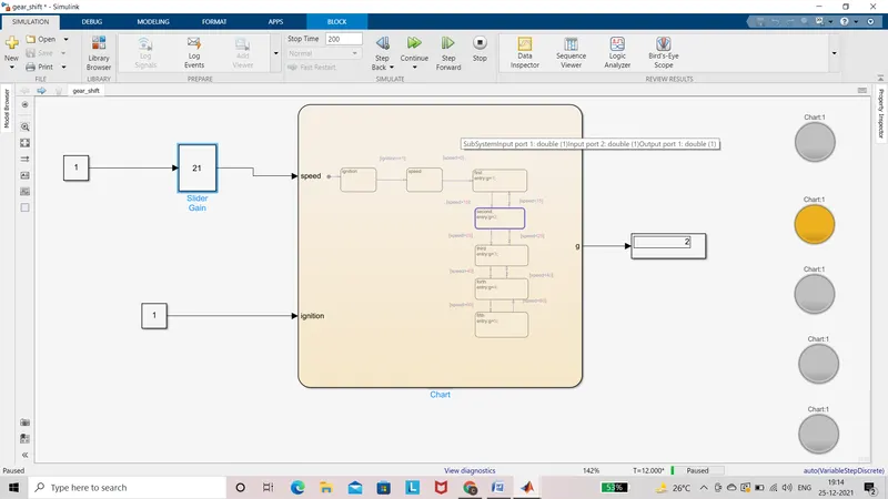
Second gear:-
When the speed range is 16 at that time 2nd gear shifted and it will be shown is display bock simultaneously lamp is glowing.
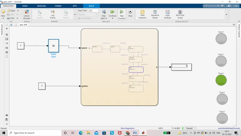
Third gear:-
When the speed range is 26-40 at that time 3srd gear shifted and it will be shown is display bock simultaneously lamp is glowing.
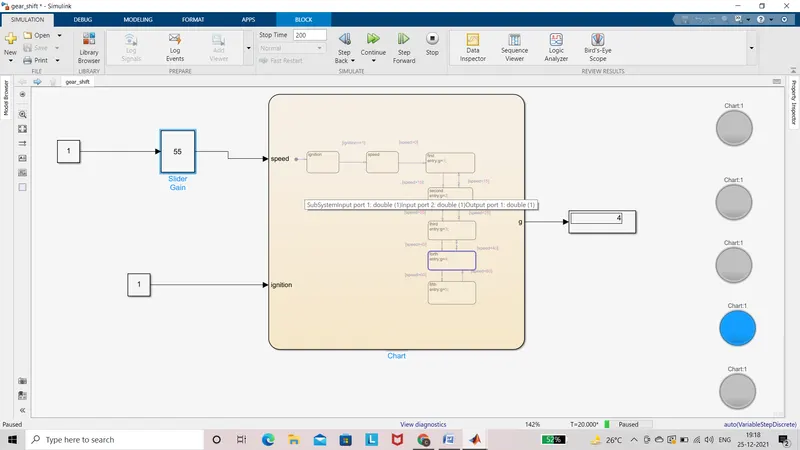
Fourth gear:-
When the speed range is 41-60 at that time 4th gear shifted and it will be shown is display bock simultaneously lamp is glowing.
Fifth gear:-
When the speed range is above 60 at that time 5th gear shifted and it will be shown is display bock simultaneously lamp is glowing.