Week -2
AIM:
- To determine the movement of the doorbell plunger using Simulink.
- Sense the temperature of the heater by thermistor using Simulink
OBJECTIVE:
- To determine the movement of the doorbell plunger by making the Simulink model.
- Sense the temperature of the heater by thermistor using various Simulink blocks.
STUDY 1:
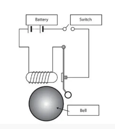
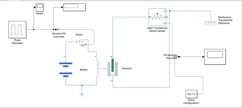
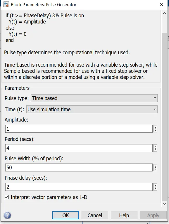
In fig., it consists of a battery, switch, solenoid, and plunger. We need to identify the movement of the plunger according to the condition given ie. The switch is closed for 2 seconds and then released. By using Simulink the input is given as a pulse generator which is connected to switch input. The switch terminals are connected to the DC voltage source and solenoid respectively. A solenoid is a coil of insulated wire wound on a rod-shaped form made of solid iron, which produces a magnetic field when an electric current passes through it. It is an electromechanical device. Devices of this kind can be used as electromagnets, as inductors in electronic circuits, etc. The solenoid plunger is connected to the ideal translational motion sensor which senses the motion of the plunger.
SIMULINK MODEL
VARIABLES:
OUTPUT RESULT:
STUDY 2:
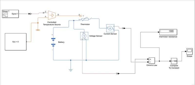
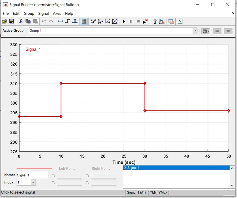
The above model consists of a DC voltage source, Thermistor, resistor, voltage sensor, reference, controlled temperature source, temperature sensor, converters, display, scope, and signal builder. Signal builder is used as the input given to achieve the condition (Temperature source: 20 °C from 0 to 10 seconds, 27 °C from 10 to 30 seconds, 23 °C from 30 to 50 seconds Fan conditions: ON if the temperature above 25 °C, OFF otherwise). Input from signal builder supplies to the temperature-controlled source which is connected to the temperature sensor. The temperature source is connected to the thermistor and temperature sensor. A thermistor is used to sense the change in resistor value which in turn change in temperature. A thermistor is a type of resistor whose resistance is dependant on temperature, more so than in standard resistors. The word is a combination of thermal and resistor. Thermistor and resistor are connected in series which is connected to DC voltage source as input. To measure The output voltage, a voltage sensor is used which controls the fan by sensing threshold value.
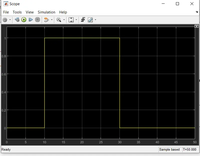
Here we add the voltage sensor connected across the thermistor. The current sensor is connected parallel to the thermistor. The output of both the current sensor and voltage sensor is connected to the divided block and creates ‘Ohm’s Law’ so that resistance in a form of output we got and it’s connected to the compare block. In that block, we set a threshold value so that switching occurs. And we get output. That output is shown in scope.
INPUT SIGNAL:
OUTPUT SIGNAL:
CONCLUSION:
STUDY:1
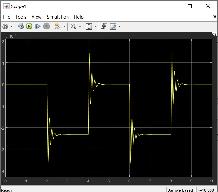
The movement of the plunger is obtained by switching the ‘ON’ or ‘OFF’ of the battery supply. the initial position of the plunger is ‘0’ and it’s and at 10sec.
STUDY 2:
The fan is controlled by using a thermistor and the temperature changes are also obtained by using the signal builder. the switch is ‘OFF’ for 0-10 secs ans ’ON’ for 10-30 secs and again ‘OFF’ for 30-50 sec. because when the temperature is above 298 K the fan will be ON either OFF