Week - 4
PROJECT-1
AIM: To Implement a control logic of a “washing machine” using Stateflow as per the given sequence.
- If the power supply is available, the system gets activated.
- If the Water supply is not available, stop the process & indicate through LED.
- Soaking time should be 200s followed by Washing time of 100s.
- Then rinsing happens for the next 20s & dryer runs for 50s.
- After all the processes have completed turn on the finished LED
THEORY:
Washing machine is a machine which is capable of handling various tasks like soaking, washing, rinsing, drying within a short period of time.
MODEL EXPLANATION:
- To create the control system in Simulink, insert the chart and create the logic system using stateflow. The stateflow executes the flow of inputs "if" the condition is accepted.
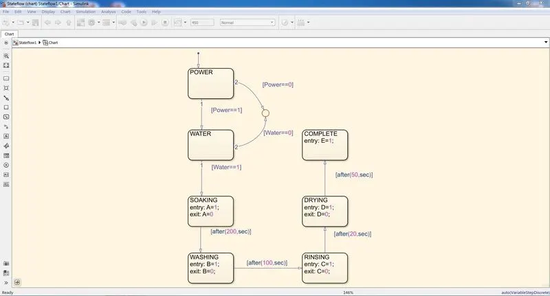
- To start with the charts we require a breakpoint added with chart Power.
- From power to water we make a loop with conditions if power is one the flow of current goes to engage the water and when the water has one condition the washing machine cycle runs from soak till the end.
- When both power and water are at 1 then the soaking process starts and run for 200 sec after this washing started.
- After 200sec the rinsing process starts and after this process, the drying process is started.
- After completing all the process, the machine turns off.
- For all the different process of the machine, the lamp indicates green for working and red for not working.
RESULTS:
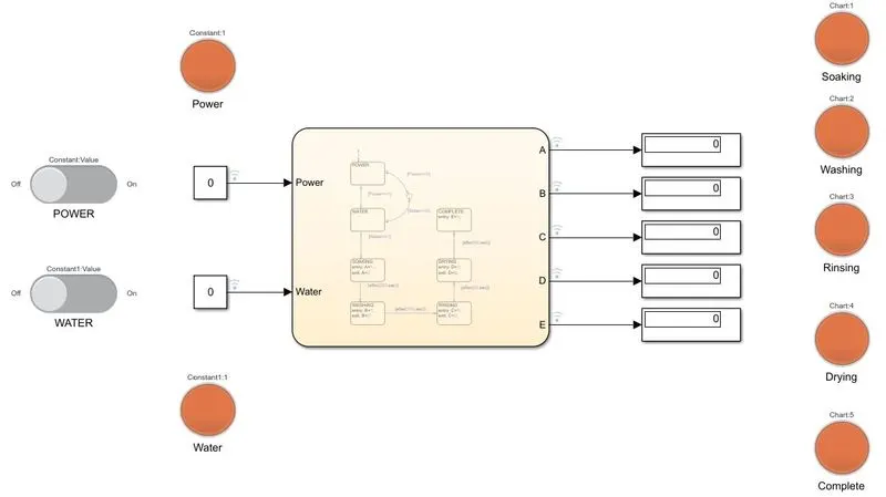
CASE-1
In this case both the power supply and water supply are assigned as 0 value, the ouput value of all operations become zero.
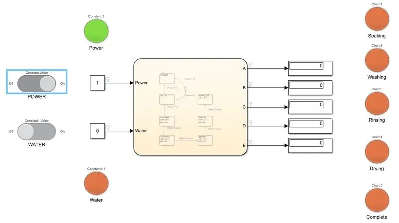
CASE-2
In this case power supply is assigned as value 1 and water supply remains 0.
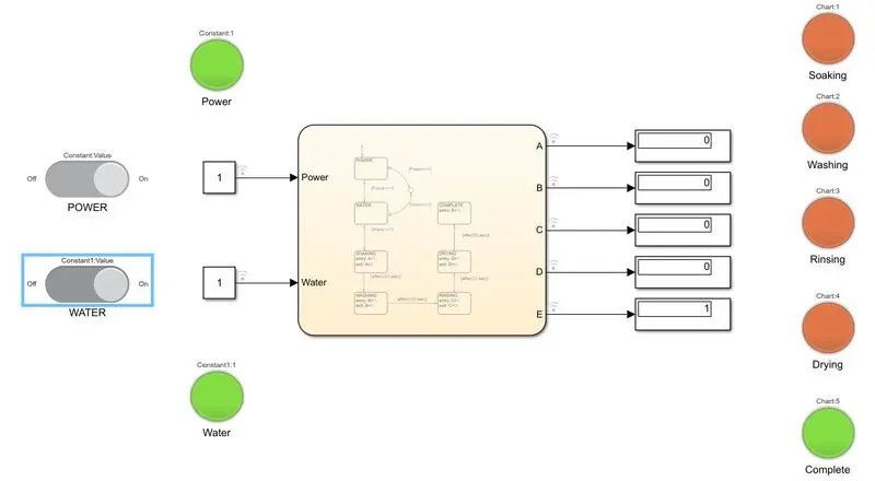
CASE-3
In this case both the power supply and water supply value are assigned as 1. The sequence of operation in stateflow starts when the condition is getting satisfied. Each operation is completed successfully and results are obtained in display block. Lamp is turned "ON" and it indicates green color.
PROJECT-2
AIM: Make a Simulink chart for the “Gear shift” logic as per below conditions:
Speed Range(kmph) Gear
0 to 15 1
16 to 25 2
26 to 40 3
41 to 60 4
Above 61 5
Give speed input while the simulation is running & display the gear number.
THEORY:
A manual transmission, also known as a manual gearbox is a type of transmission used in motor vehicle. It uses a driver-operated clutch, usually engaged and disengaged by a foot pedal or hand lever, for regulating torque transfer from the engine to the transmission; and a gear selector that can be operated by hand.
MODEL EXPLANATION:
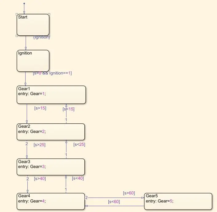
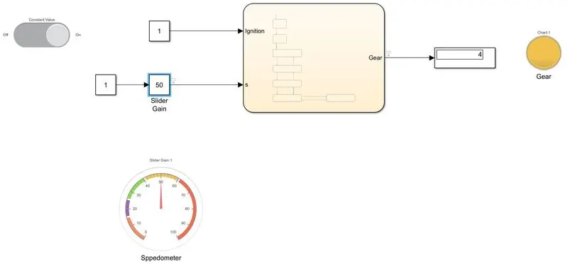
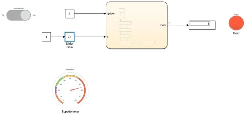
- In this model inputs are generated to slider gain which is connected to constant block the value is 1. The gear shift is acted by conditions in stateflow.
- According to the given data,
- The range of the first gear is 0-15kmph.
- The range of the second gear is 15-25kmph.
- The range of the third gear is 25-40kmph.
- The range of the fourth gear is 40-60kmph.
- The range of the fifth gear is greater than 60kmph.
- The gear is shifted by variations in speed. A speed range is created in chart as several gear system and conditions are applied.
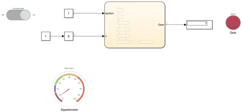
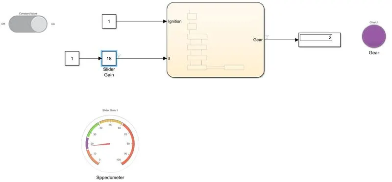
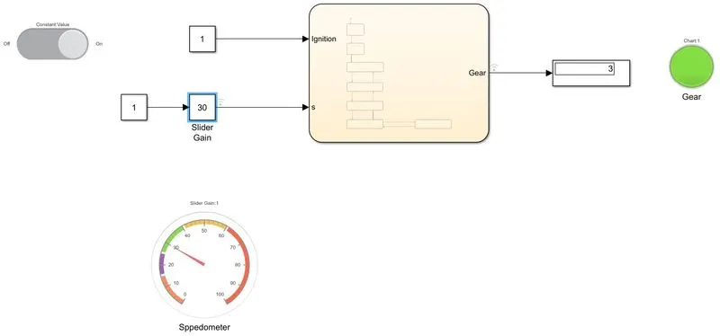
- Display block is used to display in which gear the system is running.
RESULTS:
First gear
Second gear
Third gear
Fourth gear
Fifth gear
SIMULATION FILES:
https://drive.google.com/file/d/1pH9y9uHQ85iXr0PTn-4kYo6ucIvBQ5GD/view?usp=sharing
https://drive.google.com/file/d/1vvjQi-jeEQLRXieWAkkmekvgRHLZqWmm/view?usp=sharing