Week -2
PART-1
AIM: To simulate a Simulink model of a Doorbell using Solenoid block and observe the output.
THEORY:
A simple construction of a doorbell is as shown in the figure below.
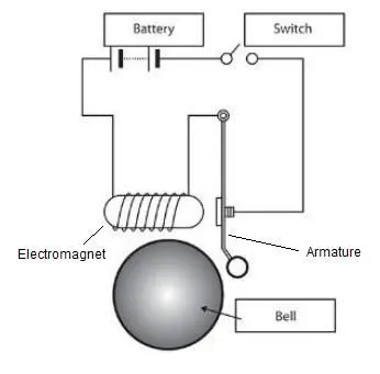
When the switch is pressed, the circuit is completed and the electromagnet is activated which makes the plunger to move which in turn pulls the metal arm to hit the bell to produce the sound. The armature is made of iron which attracts the magnet when the circuit is completed. The iron armature is connected to the spring which maintains its position and not always in contact with the bell.
Solenoid:
A solenoid is a copper wire wounded around the solenoid iron core which turns into a magnet when electricity is passed through it. The iron core demagnetizes once the electricity is cut off.
MODEL EXPLANATION:
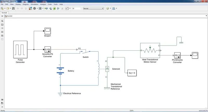
- We need a switch, battery, solenoid and plunger to complete the model.
- First a ‘Solenoid block’ is taken from simscape to represent a solenoid in the model, then a ‘Battery block’ from the library browser.
- The ‘Solenoid block’ and ‘Battery block’ is connected through the positive and negative terminals.
- A ‘Switch block’ is used between the ‘Solenoid block’ and ‘Battery block’.
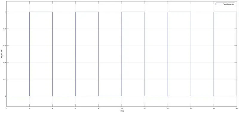
- To provide a physical signal for operating the switch, a ‘Pulse Generator block’ is used which generates a continuous square pulse.
- The given period value is ‘4’, pulse width is ‘50’, phase delay as ‘2’ and amplitude as ‘1’.
- To the ‘Pulse Generator block’ a ‘Scope block’ is connected to see how the pulse is generated.
- The pulse that is coming from ‘Pulse Generator block’ is a Simulink value, so to convert this value into physical value a ‘Simulink to PS converter’ block is used.
- The battery, switch and solenoid path is connected to ‘Electrical Reference block’ which represents the earthing of the circuit.
- A ‘Ideal Translational Motion Sensor block’, is used which senses the position of the plunger.
- The ‘Solenoid block’ ‘R’ is connected to ‘R’ of the ‘Ideal Translational Motion Sensor block’.
- The ‘Ideal Translational Motion Sensor block’ outputs are represented as V and P which represent the velocity and the position of the plunger. Since, we need only the position of the plunger, ‘P’ is connected to output.
- The ‘C’ in the ‘Ideal Translational Motion Sensor block’ and “Solenoid block’ represents the mechanical translational conversion port hence it is connected to the same ‘Mechanical Translational Reference block.
- The pulse starts after 2 seconds, then for next two seconds it has amplitude of ‘1’ and then for the next two seconds the pulse is zero.
- When the amplitude is one, the switch will be closed and when it is zero the switch will open.
- A ‘Solver Configuration block’ is connected which generates equations and solves the whole model internally to give the results of the whole Simulink model as output.
MODEL:
INPUT SIGNAL:
OUTPUT:
CONCLUSION:
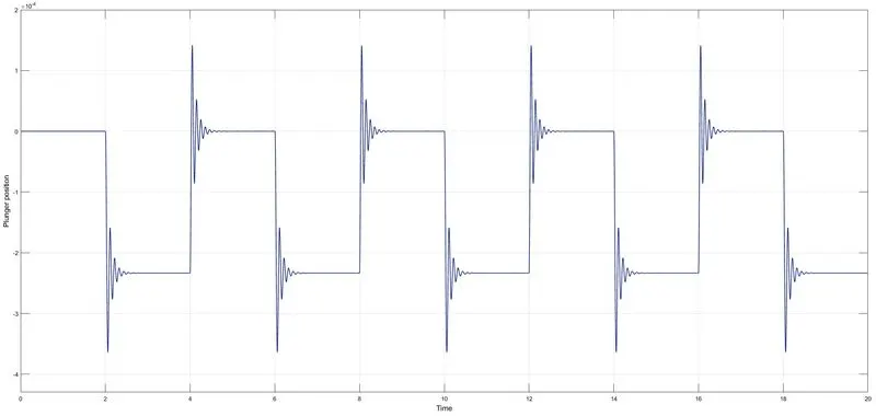
The switch is closed for 2 seconds and then released, the plunger position is noted accordingly. There are few fluctuations in the graph which is due to damping in the spring. The fluctuations can be reduced by varying the spring stiffness and dampening co-efficient value.
PART-2
AIM: To simulate working of a fan under different temperature conditions using a Thermistor in Simulink.
THEORY:
A thermistor (or thermal resistor) is defined as a type of resistor whose electrical resistance varies with changes in temperature. Although all resistors resistance will fluctuate slightly with temperature, a thermistor is particularly sensitive to temperature changes.
Some of the most common uses of thermistors include:
- Digital thermometers (thermostats)
- Automotive applications (to measure oil and coolant temperatures in cars)
- Household appliances (like microwaves, fridges, and ovens)
- Circuit protection
- Rechargeable batteries (ensure the correct battery temperature is maintained)
There are two types of thermistors:
- Negative Temperature Coefficient (NTC) Thermistor
- Positive Temperature Coefficient (PTC) Thermistor
NTC Thermistor
In an NTC thermistor, when the temperature increases, resistance decreases. And when temperature decreases, resistance increases. Hence in an NTC thermistor temperature and resistance are inversely proportional. These are the most common type of thermistor.
PTC Thermistor
A PTC thermistor has the reverse relationship between temperature and resistance. When temperature increases, the resistance increases. And when temperature decreases, resistance decreases. Hence in a PTC thermistor temperature and resistance are inversely proportional.
MODEL EXPLANATION:
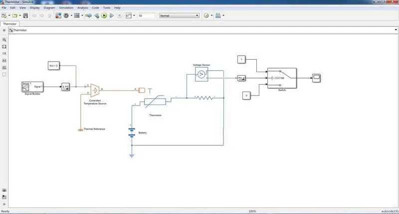
- A ‘Thermistor block’ and a ‘Battery block’ is taken and the positive port of this block is connected to positive port of the ‘Thermistor block’.
- A ‘Resistor block’ is taken from the library browser and its positive port is connected to negative port of the ‘Thermistor block’.
- The negative port of ‘Resistor block’ is connected to the negative port of the ‘Battery block’.
- An ‘Electrical Reference block’ is connected near the negative terminal of the ‘Battery block’ which represents the earthing.
- A ‘Voltage Sensor block’ is connected parallel to the ‘Resistor block’.
- To provide temperature, we have used ‘Controlled Temperature Source block’ which gives a specified temperature as output
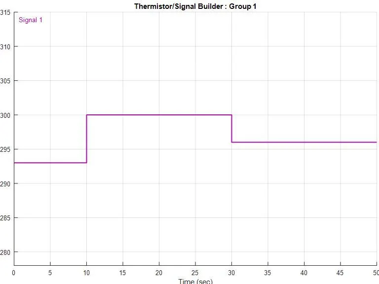
- To send temperature signals we have used a ‘Signal Builder block’.
- The port ‘B’ of ‘Controlled Temperature Source block’ is connected to port ‘A’ of the ‘Thermistor block’ and port ‘A’ of ‘Controlled Temperature Source block’ is connected to the a ‘Thermal Reference block’.
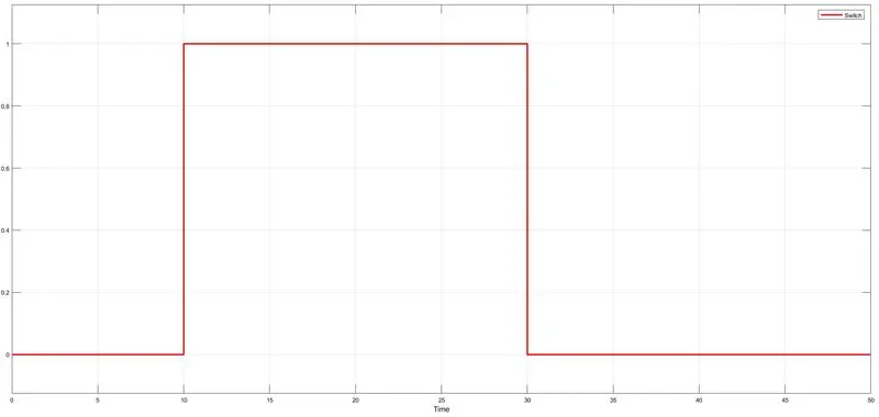
- The objective is that fan should be ON when temperature is more than 25°C and the fan should be OFF when temperature is below 25°C.
- The center port of ‘Switch block’ is connected to output of ‘PS-Simulink Converter’ which gives the voltage values. The top port of the ‘Switch block’ is connected to a ‘Constant block’ of value 1 and bottom port of the ‘Switch block’ is connected to another ‘Constant block’ of value 0.
- The center port of ‘Switch block’ is the condition input which means that when the value from ‘Voltage Sensor block’ is more than the threshold value in the ‘Switch block’ then it will pass the value 1 which we have specified in the top port of the ‘Switch block’. If the voltage from ‘Voltage Sensor block’ is less than the threshold value in the ‘Switch block’.
- The threshold value is set at 0.01189 i.e. output from voltage source block for 25°C.
MODEL:
INPUT SIGNAL:
OUTPUT:
CONCLUSION:
From 0-10 seconds fan is OFF because the temperature is 293K which is below 298K, after 10 seconds it goes to 300K, so fan will turn ON because temperature exceeds 298K. After 30 seconds fan will turn OFF because temperature goes 296K which is less than 298 K.
ERRORS:
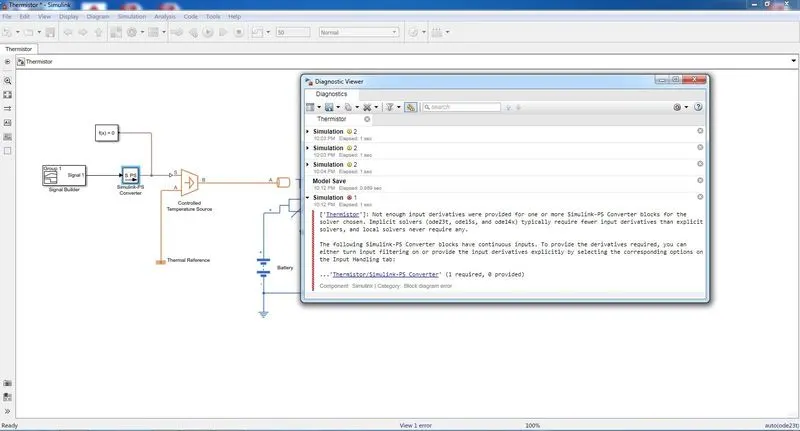
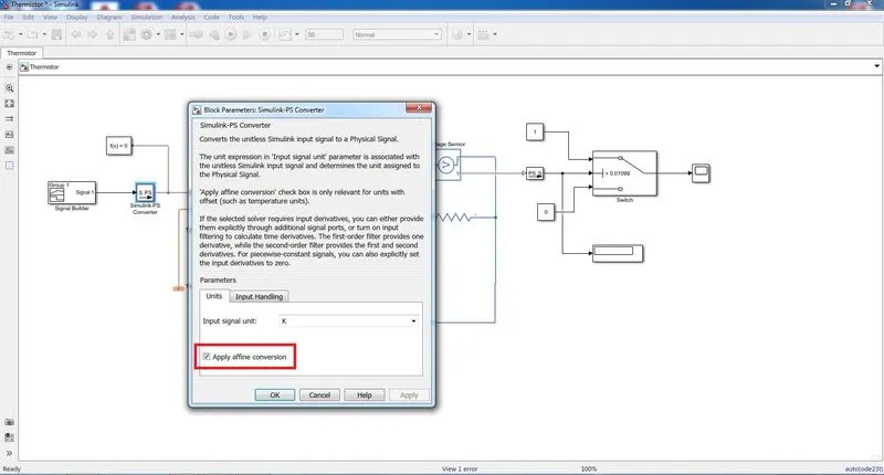
The above error was resolved by checking the 'Apply affine conversion' and in Input Handling, filter inputs derivative calculated option is selected.
SIMULINK MODEL LINKS:
https://drive.google.com/drive/folders/1bIc5zVYOluf6-UxXAawzQpZNKE96-cvg?usp=sharing