Week - 4
1.Implement control logic of a “washing machine” using Stateflow as per given sequence:
- If the power supply is available, the system gets activated
- If the Water supply is not available, stop the process & indicate through LED
- Soaking time should be 200s followed by Washing time of 100s.
- Then rinsing happens for next 20s & dryer runs for 50s
After all the processes have completed turn on the finished LED
State flow
Stateflow (developed by MathWorks) is a control logic tool used to model reactive systems via state machines and flow charts within a Simulink model. Stateflow uses a variant of the finite-state machine notation established by David harel, enabling the representation of hierarchy, parallelism and history within a state chart. Stateflow also provides state transition tables and truth tables.
Stateflow is generally used to specify the discrete controller in the model of a hybrid system where the continuous dynamics (i.e., the behavior of the plant and environment) are specified using Simulink.
Specific applications for Stateflow include:
- Mode logic, where each discrete mode of a system is represented by a state
- Fault management, where the Stateflow chart is used to control how the system responds to faults and failures within a system
- Task scheduling, where the Stateflow chart is used to schedule when specific tasks occur, either within the Stateflow chart or within the overall Simulink model
Control logic
Control logic is the part of a controller that defines how a reactive system responds to events or conditional changes. Applications for control logic include: Supervising how to switch between different modes of operation.
Automatic washing machine
An automatic washing machine is a perfect example of a state flow system with implementation of control logic. The whole process of washing would include Soaking, washing, rinsing, and then Spinning(drying).
Simulink model
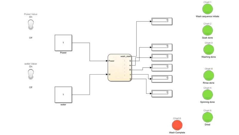
The above image shows the Simulink model created to represent the working of an automatic washing machine. As you can see there are indicator lamps to show each state of the washing machine. And when the process is done another lamp switches on (orange color).
The chart for the Automatic washing machine which contains the conditions for each state is given below.
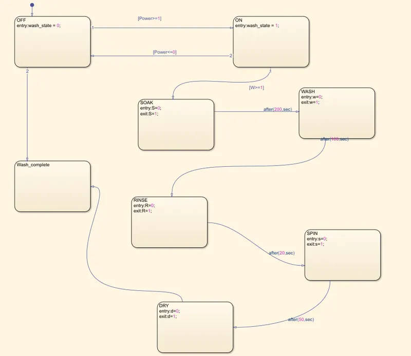
Blocks used for this model
1. Toggle switch- for power and water supply
2.Constant - for the constant power supply and water supply
3. Flowchart - This contains the conditions with which the states hsould change.
4. Display - Which shows us the real-time state
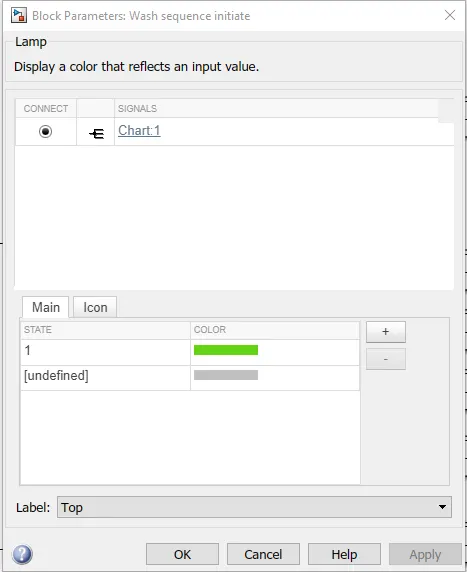
5. Lamp - to show what states are done/in process.
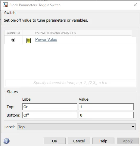
Power switch
Lamp 1 Condition
Working
>With the toggle switch on for the power and water supply the flow chart will get compiled
> the signals with which the switches are defined is 0 and 1. 0 being off and 1 being on.
> If either one is 0, then the washing will not continue.
> when both signals are showing 1, then the soaking process begins for 200s
> followed by washing for 100s, which is then followed by rinsing.
> After the aboves states are done it moves on to drying(or spinning)
> After the last state(drying), the Led lamp at the end (orange) indicatesa that the washing is done.
2. Make a Simulink chart for the “Gear shift” logic as per below conditions:
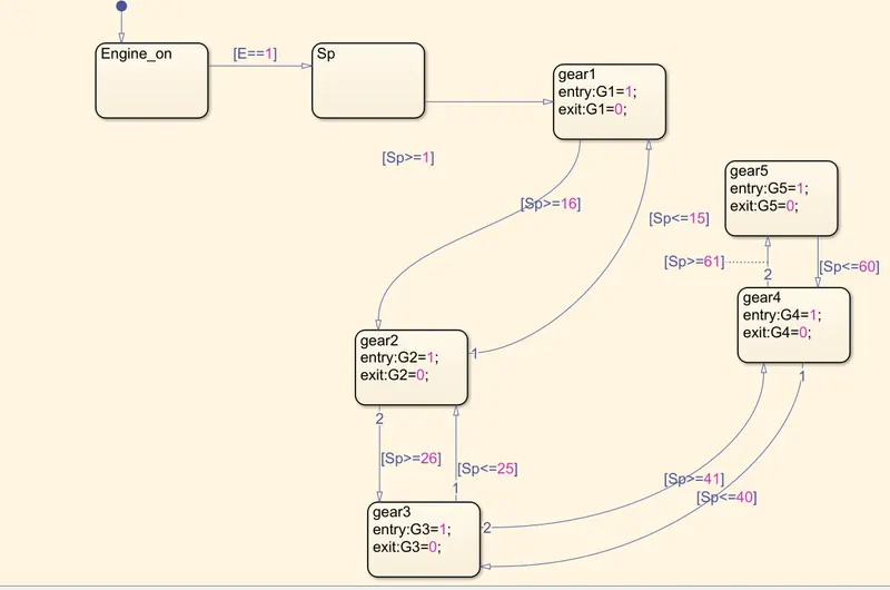
Speed Range(kmph) Gear
0 to 15 1
16 to 25 2
26 to 40 3
41 to 60 4
Above 61 5
Give speed input while the simulation is running & display the gear number.
Gear box and Gear shifting
Generally, there are two sets of gears in a conventional gear box – the input & the output. The input gears are fixed on the countershaft, making it a single unit. It drives the individual gears on the main shaft, which rotate freely on the bearings. Thus, the gearbox passes the drive to the wheels depending upon the gear which engages on the main-shaft. When you push the shifter-sleeve towards the desired gear, that gear locks onto the main-shaft and rotates it. Thus, the main shaft rotates at the engaged gear's speed and provides the output as per the engaged gear’s ratio.
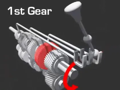
Our model should indicate which gear the system is in dwepending on the speed of the input shaft. Each gear is indicated with a lamp.
The model for the same is given below
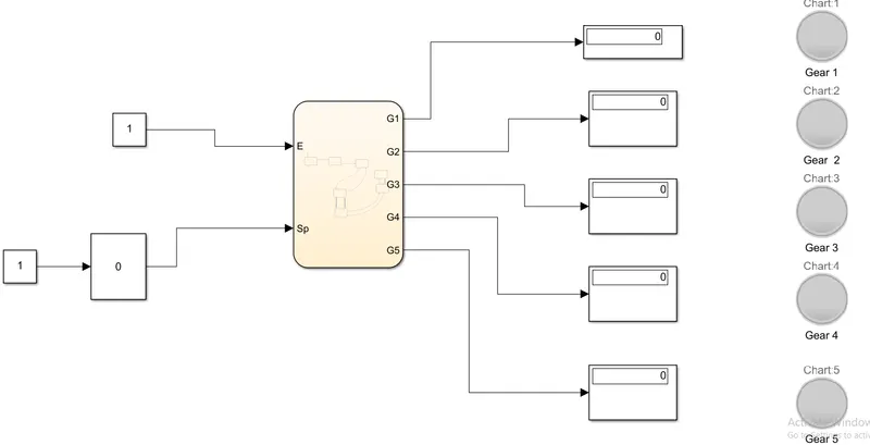
The flow chart for the conditions of gear selection is below
Blocks used
1. Constant
2. Slider gain - to give speed input in real time
3.Display - to show which lamp is switching on with the speed.
4. Flowchart- This contains the conditions of speed and gear selection.
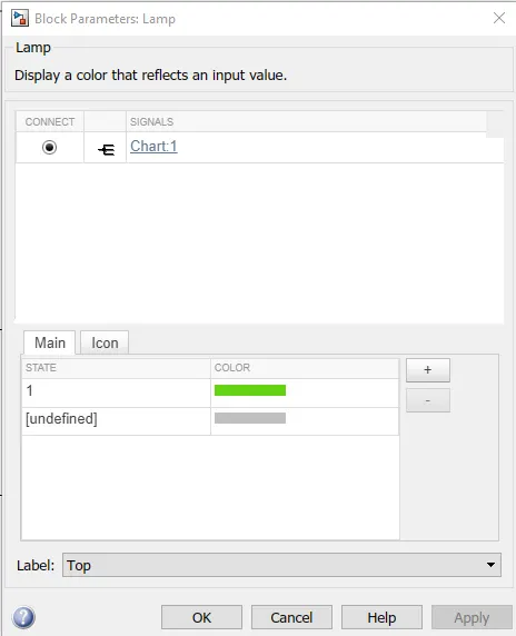
5. Lamp - indication of gear position.
Lamp connection.
Procedure
> With the Two constant blocks with the value as 1, the engine will be on, and the other constant block is for the initial condition of the slider gain.
> The simulation stop time should be kept to infinity as we have to change the speed in real time.
> With inf as the simulation time afetr you run the model and the comiling is done you can double click the slider gain and adjust the speed with which the conditions are given.
> When the speed conditions are met for each gear the led lamp for that gear number will light up.
*Both the files are attached to this report*