Week - 4
AIM:
-
IMPLEMENTATION OF THE CONTROL LOGIC FOR WASHING MACHINES USING STATEFLOW.
-
IMPLEMENTING THE GEAR SHIFT LOGIC USING THE STATEFLOW.
OBJECTIVE:
-
Implementing the control logic for the washing machine using the Stateflow as per the given conditions-
- If the power supply is available, the system gets activated.
- If the water supply is not available, stop the process and indicate through the LED.
- Soaking time should be 200s followed by a washing time of 100s.
- Then rinsing happens for the next 20s and dryer runs for the 50s.
- After all the processes have been completed, turn ON the finished LED.
2. Make Simulink chart for the Gear shift logic as per below conditions-
Speed Range(kmph) Gear
0 – 15 1
16 – 25 2
26 – 40 3
41 – 60 4
61 & Above 5
Give the speed input while the simulation is running and display the gear number.
THEORY:
1. Washing Machine Stateflow -
A washing machine is a machine used to wash various types of clothes without applying any physical effort. With a washing machine, you don't have to rub the clothes with your hand or squeeze them to remove the water from them. It enables us to wash our clothes without having to supervise its operation. All we've to do is put the clothes on the machine and select the wash mode, put in the dirty clothes, set the timer and put some detergent. The washing machine will automatically take the required amount of water and will do the soaking, washing, rinsing and drying.
Modelling of Washing Machine in Simulink -
Blocks that are used for making the Simulink model of the washing machine are:
-
Constant Block
-
Chart Block
-
State Flow Block
-
-
Toggle Switch Block
-
Scope Block
-
Lamp Block
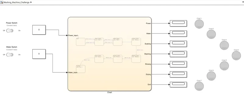
State Flow chart
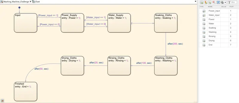
For making the Simulink model of the washing machine, first, we create a Chart Block. By double-clicking the chart block, we will enter a space where we can build our state-flow blocks. Inside the chart block, we'll create 8 state blocks namely for
-
Input: Block from where input power will be given. [(Power_input == 1), if the power input condition is not equal to 1 or is 0, then the 2nd condition or the next step will not be performed.]
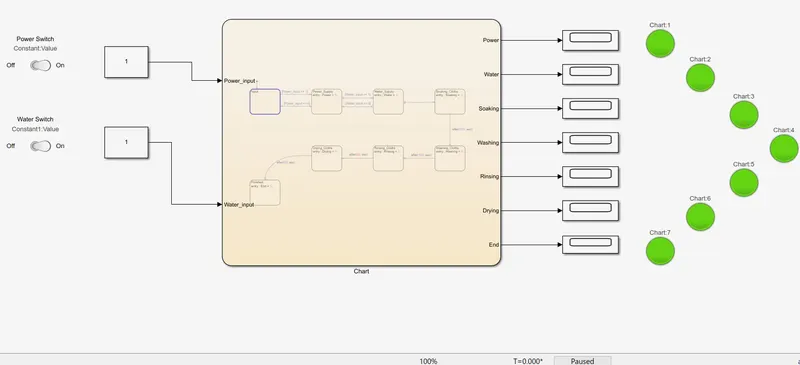
-
Power Supply: Block where Power Supply condition will be checked (Power = 1)
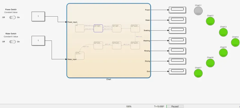
- Water Supply: Block where Water Supply condition will be checked (Water = 1) [(Water_input == 1), if the input condition is mot 1 or is 0 then the 3rd condition or the next step will not be performed.]
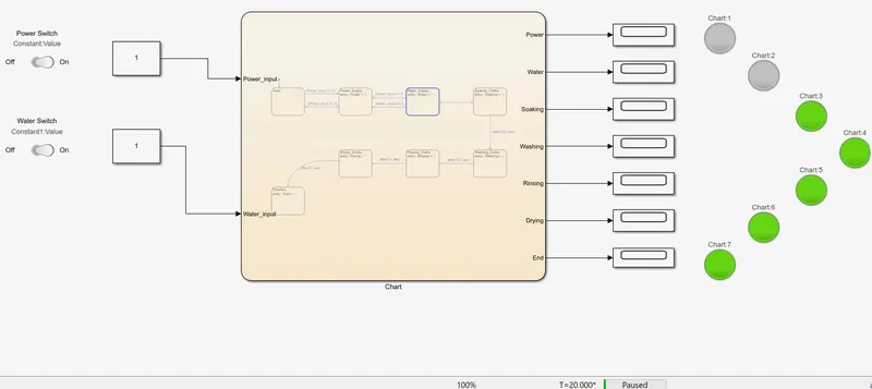
-
Soaking: Block where Soaking condition will be checked/performed for 200 secs(Soaking = 1).
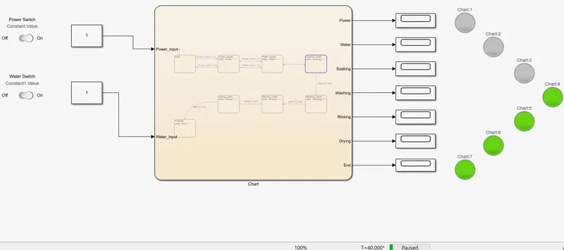
- Washing: Block where washing condition will be checked/performed for 100 secs(Washing = 1).
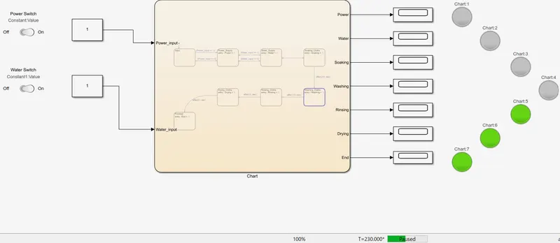
- Rinsing: Block where rinsing condition will be checked/performed for 20 secs(Rinsing = 1).
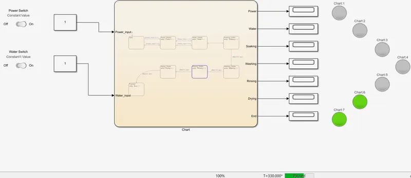
- Drying: Block where the Drying condition will be checked/performed for 50 secs(Drying = 1).
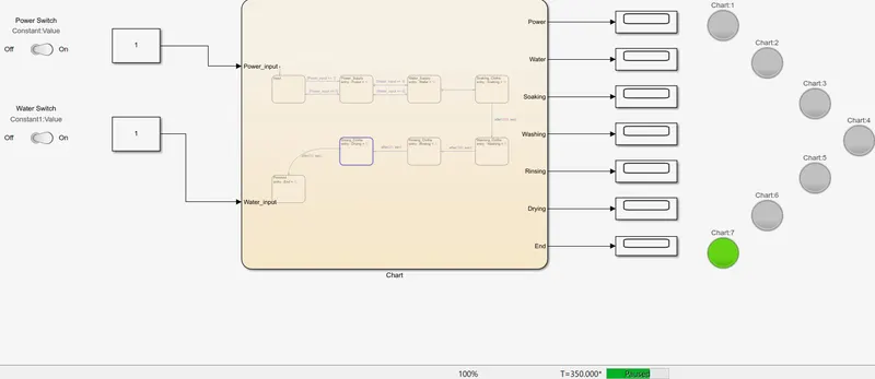
- Finish: Block where the End process will be checked (End = 1).
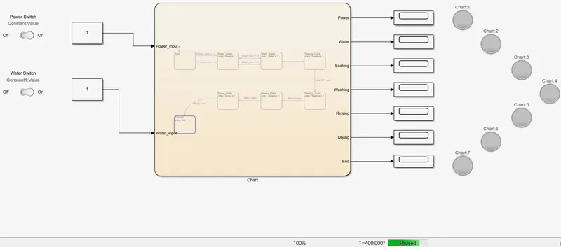
2. Gear Shift Logic -
A gear shift mechanism for a manual transmission includes a shaft axially movable for selecting shift planes and rotatable for engaging the gears defining the shift planes. The shaft is held in a reference shift plane by 2 helical springs.
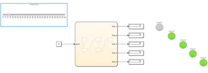
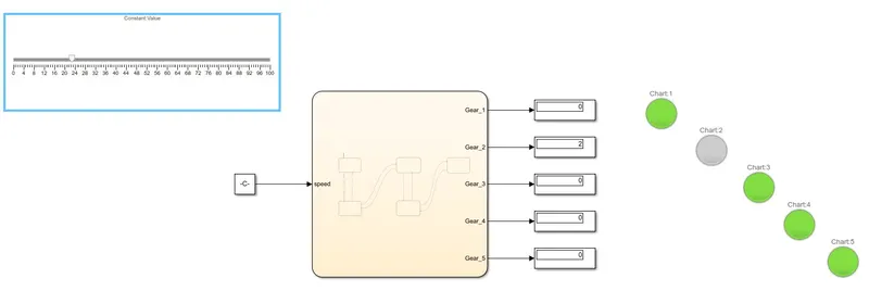
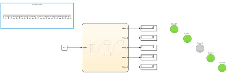
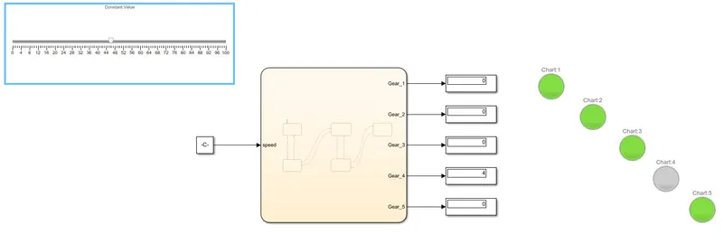
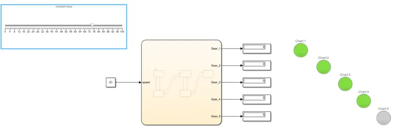
For making the Simulink Gear shift logic, for which the given conditions are -
Speed Range(kmph) Gear
0 – 15 1
16 – 25 2
26 – 40 3
41 – 60 4
61 & Above 5
Simulink model
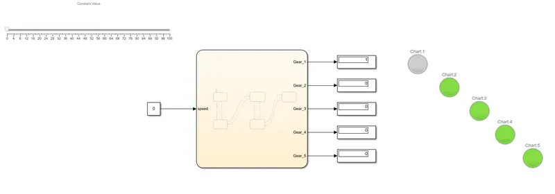
Stateflow Chart -
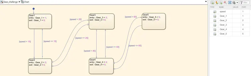
For creating the Simulink model of the Gear Shift, a Chart Block is created and by double-clicking it we will enter a space where we can build our state-flow blocks. Inside the chart block, we'll create 5 state blocks namely for -
-
Gear1
- Gear2
- Gear3
- Gear4
- Gear5
CONCLUSION:
-
Successfully implemented the control Stateflow logic for the washing machine with time intervals.
-
Successfully implemented the control Stateflow logic for the Gear Shift with the given intervals.