2D meshing for Plastic components
AIM-
For the given Plastic Bottle Cap model, check for the geometrical errors and take the mid surface by suitable mid surfacing techniques. PID and Thickness assignment has to be done for all the mid surfaces. Mesh the same with given element Quality criteria. (Refer to the table below for the Quality criteria)
|
S.No |
Quality Criteria |
Value |
|
1 |
Target/Average length |
1 |
|
2 |
Minimum Length |
0.5 |
|
3 |
Maximum Length |
3 |
|
4 |
Aspect |
3 |
|
5 |
Warpage |
15 |
|
6 |
Skewness |
45 |
|
7 |
Jacobian |
0.7 |
|
8 |
Minimum Quad Angle |
45 |
|
9 |
Maximum Quad Angle |
135 |
|
10 |
Minimum Tria Angle |
30 |
|
11 |
Maximum Tria Angle |
120 |
|
10 |
Tria Percentage |
15 |
PROCEDURE -
The actual component of which the mid-surface is to be taken is shown below.
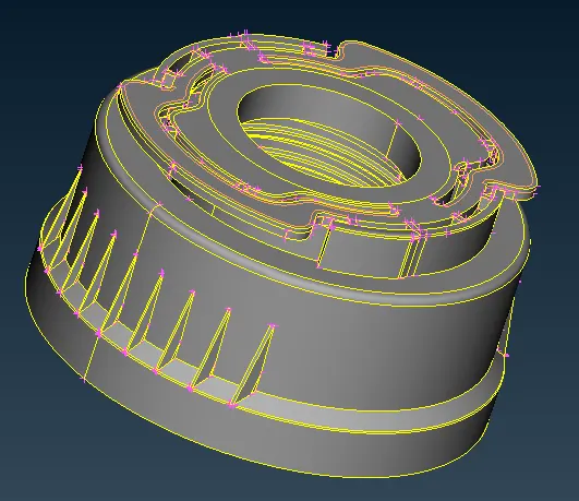
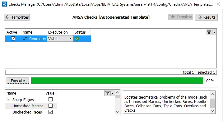
1. We first import the model and then check the geometry for any errors like a single con, needle face, crack surfaces using the Checks->Geometry tool in the menubar. Select the component and click on execute to check all the errors.
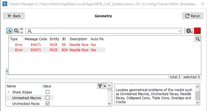
The above errors can be fixed automatically using the fix option.
2. Once the geometry check is complete, we select the mesh->perimeter-> length tool and give a value of 1 to refine the macros and perimeter of the model for a good resolution to see the component.
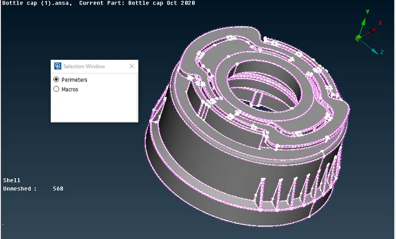
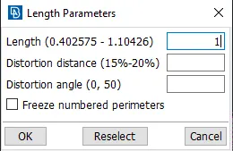
The value 1 will make sure we get the refined view of the component.
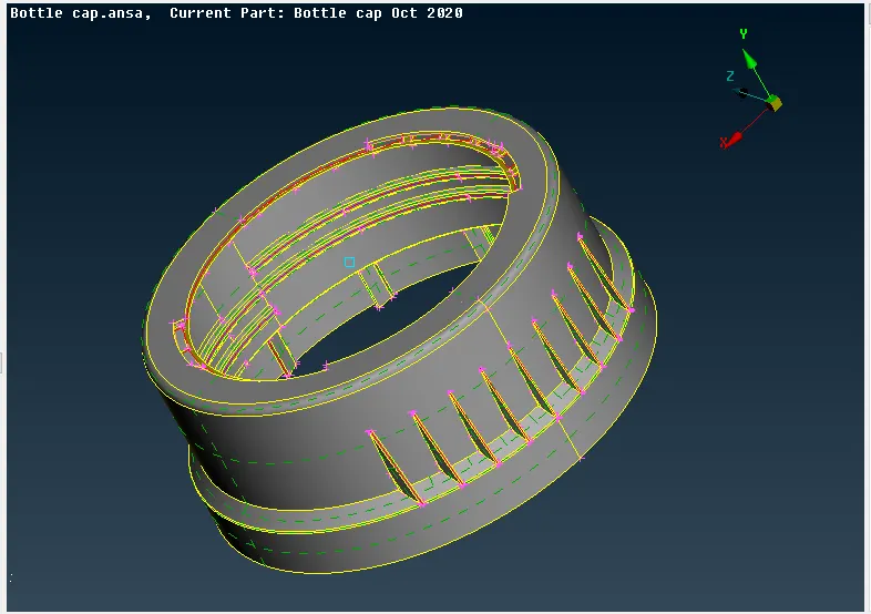
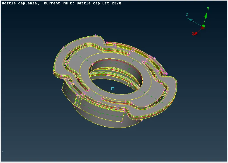
3. Now, we use the boolean tools to separate the surfaces for taking mid-surfaces as shown below.
The part was divided as bottom and top. The below image shows us the bottom part of the cap.
The below image shows us the top part of the bottle cap.
4. Next step is to take the mid-surface of these parts. For that, we need to first measure the thickness of the model to find the value of the offset.
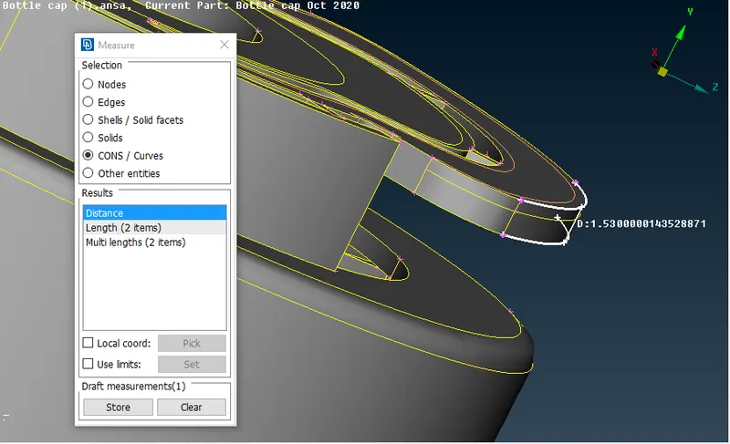
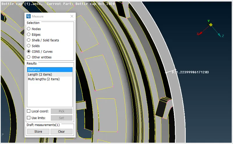
The thickness of the 2 surfaces is the same throughout in most cases. We will use the offset option from topo->faces->offset. We assign half a value of the thickness to its respective directions and select the faces to offset.
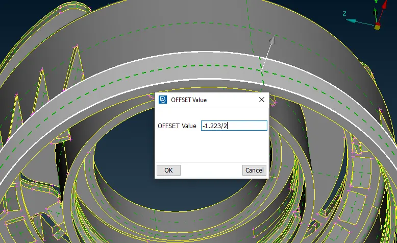
With this, a mid-surface of that selected region is obtained.
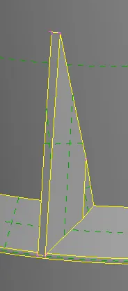
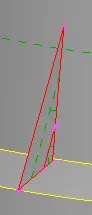
5. This model also has a varying thickness in some surfaces whose mid-surfaces are extracted by using the middle tool in topo->faces->middle-(single or multi). We can use single or multi options depending on the surfaces that are present.
The mid-surface of the ribs in the below image can be obtained by the 'single' option in the 'middle' tool.
6. The threads in the bottle cap component have a trapezium-shaped surface. The mid-surface for this is taken by first producing a mid-curve from its top surface. We do this using the topo->curve->middle. We then project the mid-curve onto the mid-surface using topo->cons->project. These curves are used to create a new surface using topo->faces->new. The mid-surface is generated for the threads.
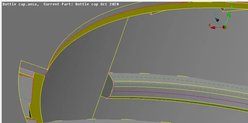
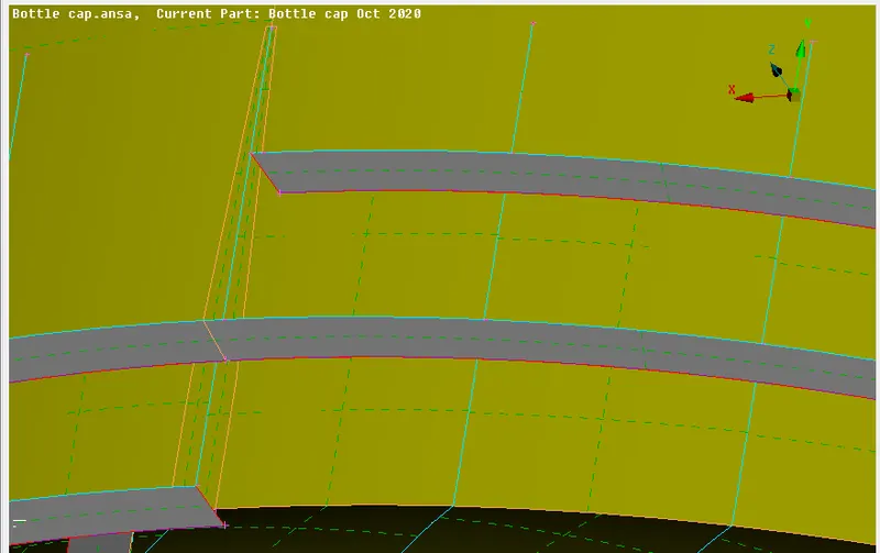
7. We have ribs of varying thickness at the inner bottom surface of the model. We use the topo->faces-middle option to get a mid-surface for the rib and now extend the free edges to the parent mid-surface using the topo-faces-extend.
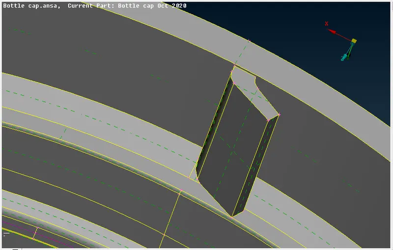
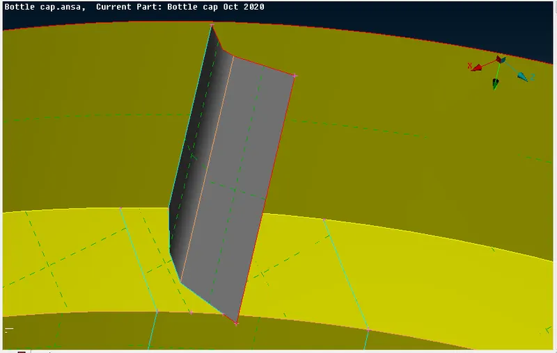
The blue cons represent the triple cons, which appear after extending its surface to the parent mid-surface.
8. We now work on obtaining the mid-surface of the teeth in the model as shown. We can use the mid-curve option to create a mid-curve in the area shown below.
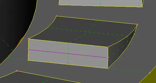
We then project the curve at the opposite of this surface onto the mid-surface and then we can create a surface using the create new surface tool.
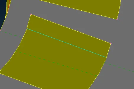
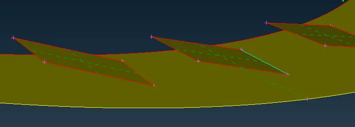
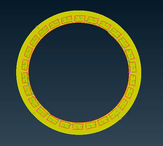
As the number of ribs is more and is arranged around the surface, we can copy the created mid-surface and rotate it around the axis of the surface to obtain the mid-surfaces of all the ribs. We can use transform->copy->rotate option.
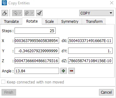
The ribs after performing the above process are shown below.
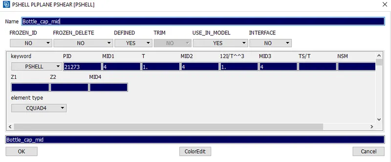
9. We need to now assign the thickness for the mid-surfaces. We can create a new property by selecting the property->new->pshell->assign thickness->assign a name.
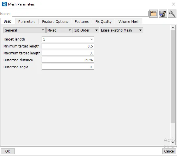
10. After this step, we move onto mesh the model. Before mesh, we need to specify the mesh parameters. The target element length is given as 1mm, minimum length as 0.5 mm, and maximum length is 3 mm which is shown below.
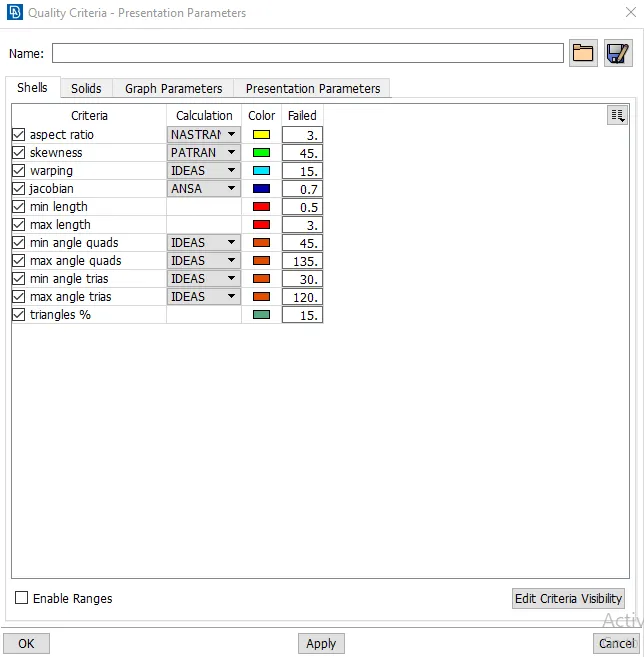
11. Quality criteria are set for the model as per the requirement. We select the quality criteria option and assign values as shown below.
12. With this, we can go ahead with the meshing of the model. First, we select the macros and select the best mesh in the mesh generation (mesh->mesh generation->best). The mesh is now generated in the selected macros. We follow the same procedure for mesh generation for the rest of the model.
We use the split, paste, swap options to reduce and clear the trias. We aim to reduce the number of opposite trias, back-to-back trias in the existing mesh.
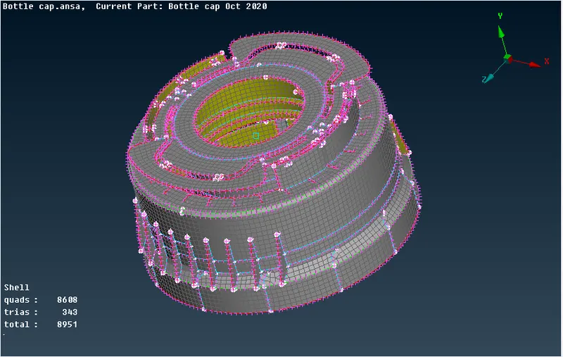
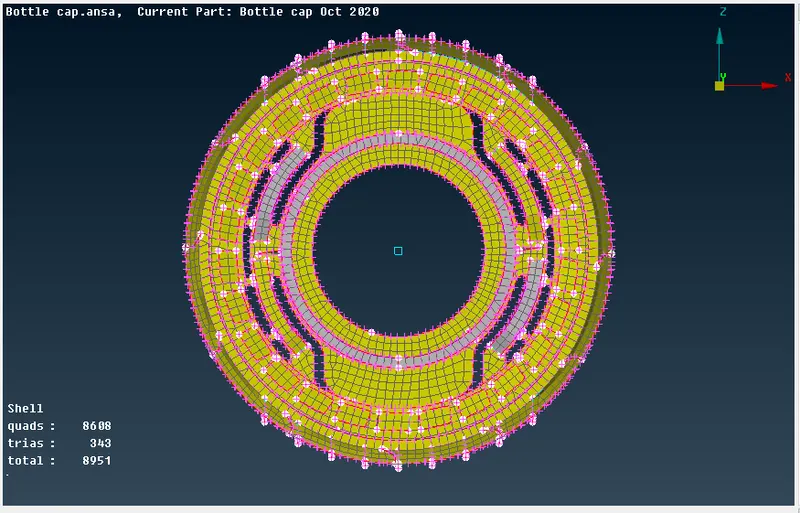
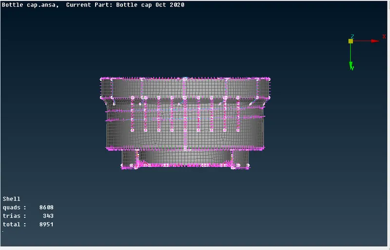
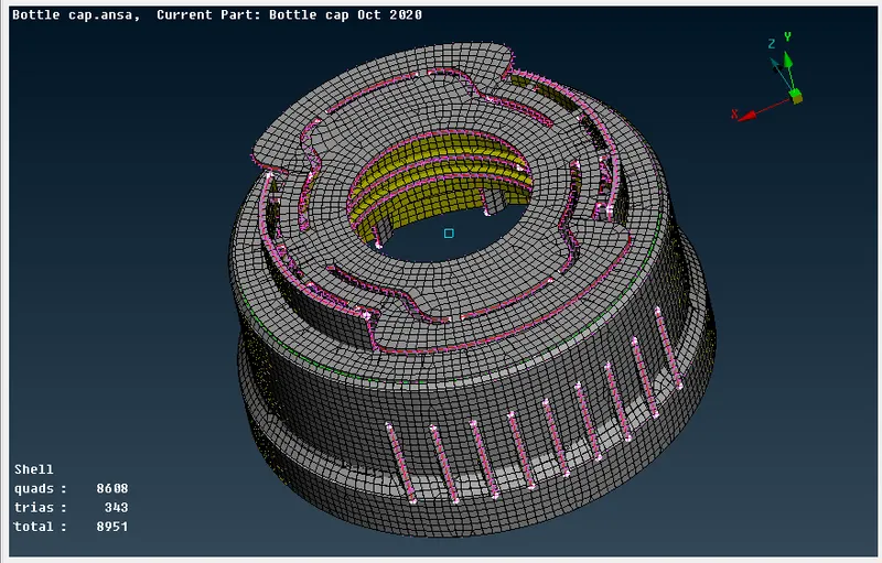
After the mesh, we need to check for the quality criteria and assess the failed elements using the tools like smooth, reconstruct, fix, quality, move in the mesh module. Some elements around the tripe cons are failed for minimum length, aspect ratio, and skewness. Those elements are found under OFF elements.
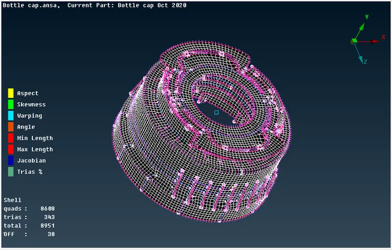
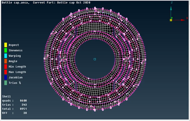
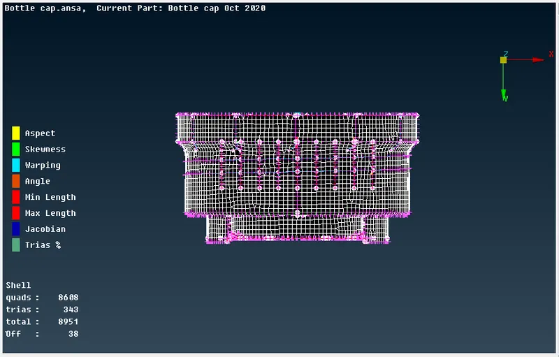
The final meshed component is shown below-
CONCLUSION -
The mid-surface of the bottle cap model is created using the various tools in the topo module and is also meshed with the given quality criteria and mesh parameters.
The model can be found in the link below.