Week - 4 - 2D meshing for Plastic components
Week 4 Challenge ANSA
2D Meshing of Plastic Bottle Cap
Aim: To extract the middle-surface of the plastic bottle cap and mesh the same with, given element quality criteria as mentioned below and also assign a proper thickness to it.
Quality criteria:
|
S.No |
Quality Criteria |
Value |
|
1 |
Target/Average length |
1 |
|
2 |
Minimum Length |
0.5 |
|
3 |
Maximum Length |
3 |
|
4 |
Aspect |
3 |
|
5 |
Warpage |
15 |
|
6 |
Skewness |
45 |
|
7 |
Jacobian |
0.7 |
|
8 |
Minimum Quad Angle |
45 |
|
9 |
Maximum Quad Angle |
135 |
|
10 |
Minimum Tria Angle |
30 |
|
11 |
Maximum Tria Angle |
120 |
|
10 |
Tria Percentage |
15 |
Model:
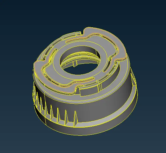
Plastic bottle cap
Objectives:
- Generating the mid-surface from the parent component
- Performing a meshing operation on a middle surface as per element quality criteria
- Checking the element quality by comparing with given quality parameters and criteria and improve the quality by various options
- Assigning the material and proper thickness to it
Theory:
Why we do Geometrical cleanup?
While we importing any geometry data it generally come up with little errors, some geometrical issues are
Surfaces are not stitched together.ie. (there is a gap present between the surfaces)
Very small surfaces are squeezed between the surfaces.
Sometimes duplicate surfaces are present
The junction between the two surfaces also contains the gaps, overlaps and misalignments.
In order to remove that issues and errors we do geometry cleanup.
Mid-Surfacing:
Why we create the Mid-surface?
While doing 2D meshing we extract the mid-surface from the model. Mid-Surface means the surface between the two surfaces. 2D meshing is carried out on the mid-surface, because mathematically element thickness we assigned half in +Z axis (element top) and half in -Z axis (element bottom). Hence for appropriate representation of geometry via 2-d mesh it is necessary to extract the mid-surface & generate nodes and elements on the mid-surface. We try to create the shell elements (one dimension i.e. thickness is significantly smaller than the other dimensions) which is 2D representation of 3D elements. Mid-Surface meshing is used when the geometry thickness is very small as compare to its length and width, so we are generally used in most of industries where structure is made up of sheet metals and plastic etc. In that cases, we use 2D elements instead of 3D elements, hence by adopting Mid-Meshing number of nodes are decreases and also computational time decreases.
We can extract mid-surface in two ways
- Manual mid-surfacing
- Automatic mid-surfacing
Here for above component, we choose manual mid-surfacing because the given model is of plastic / casted one, so thickness is not constant throughout, if we use automatic mid-surfacing and meshing it will not give us accurate result, user have to do lot changes in model to repair, so that’s why we choose manual mid-surfacing, in manual mid-surfacing we use offset option to create middle surface
During meshing we have to take care about
- Feature should be capture properly
- No back to back trias
- There should be element connectivity between the elements
- No opposite trias
- No rotational quads
- Quality check to ensure that all element are within good quality
Note: During meshing make sure to check for free edge option at regular interval. It will help us to show that where there is no element connectivity in the mesh
Plastic Meshing:
- Plastic meshing is a type of shell meshing where the thickness of the component will vary
- Mid-Surface extraction plays a major role in plastic meshing
The mid-surface extraction is somewhat tricky when compared to sheet metal meshing
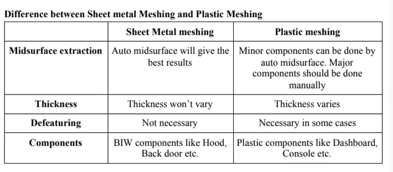
Image Source: Skill-Lync
Best practice to be followed while meshing a plastic component
- Check if the component is symmetric or not
- If it is symmetric, extract the mid-surface only for half portion
- If component is not symmetric, extract the mid-surface for whole component
- We have to check the auto mid-surface for the component, if it is not giving the better result then, we have to jump to other methods
- Split the component into simple parts and try to extract the auto mid-surface
- The distorted surface can be deleted and by using offset and extend command we can stich the surface
- If auto mid-surfacing is not doing well, then we have to do the whole component
- While extracting the whole mid-surface manually we have to be more clear about the base surface, since base surface should not having varying thickness in the most cases
- After creating the base mid-surface, we have to take a look at the ribs attached to mid-surface (we can use surface pair to generate the middle surface and extend the and extend the rib to base mid-surface
- If ribs are within same dimensions, we can use the translate rotate and position option in order to create them again.
- After that the mid-surface of critical parts like dog houses snap fits, mounting clips etc can be extracted by surface pair and offset option.
- Check the rib surface are connected properly to the base. There should be a T-Connection between the base mid-surface and ribs surface
- Meshing the surface from the complicated region and moving toward free edges
Procedure:
- Import the model file by using open option in ANSA
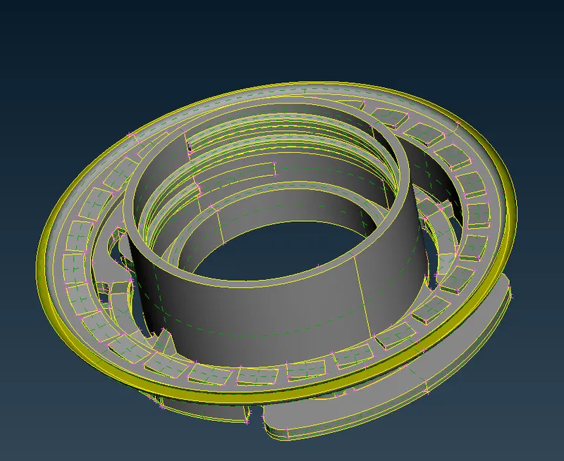
Upper part of Bottle cap
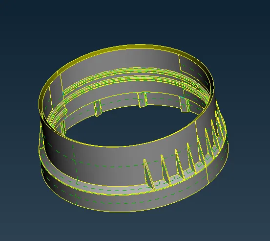
Lower part of Bottle cap
- Use the Topo option to join the edges, for better visualization
- Now we have to check the error in parent geometry, for that go to check manager > geometry for checking the geometrical issues.
- Here we have lots of Option in ANSA by which we can remove error from the geometry and creating and improving the quality of mesh
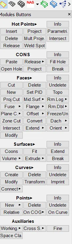
Geometry refinement tools
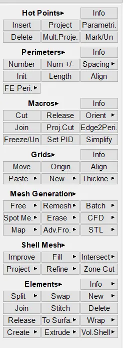
For creating and improving the mesh quality
- After cleaning the parent geometry, now we can start extracting the mid-surface of the component, before going to mid-surface option we can also hide our lock the view of geometry that we require for easy working, we can store the view by using lock option
- Now for manual mid-surfacing we, can use offset option to offset the surfaces into the middle, also we are using middle option in Face panel, to create the middle surface between two surfaces
Parent Geometry
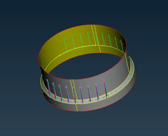
Mid-Surface of lower part of Bottle cap
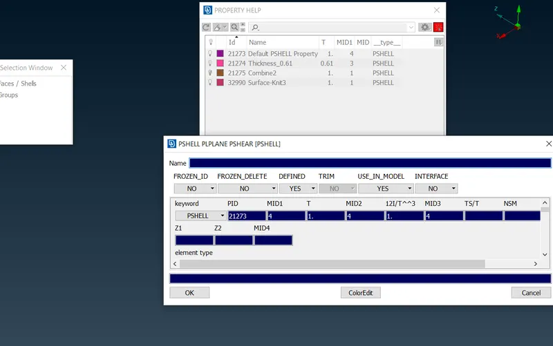
- Along with mid-surfacing, we also have assign property and thickness to the different parts of the Bottle cap
- in case of teeth, we have to only take a mid-surface of one teeth and for the rest of teeth we are using rotate command to rotate the teeth.
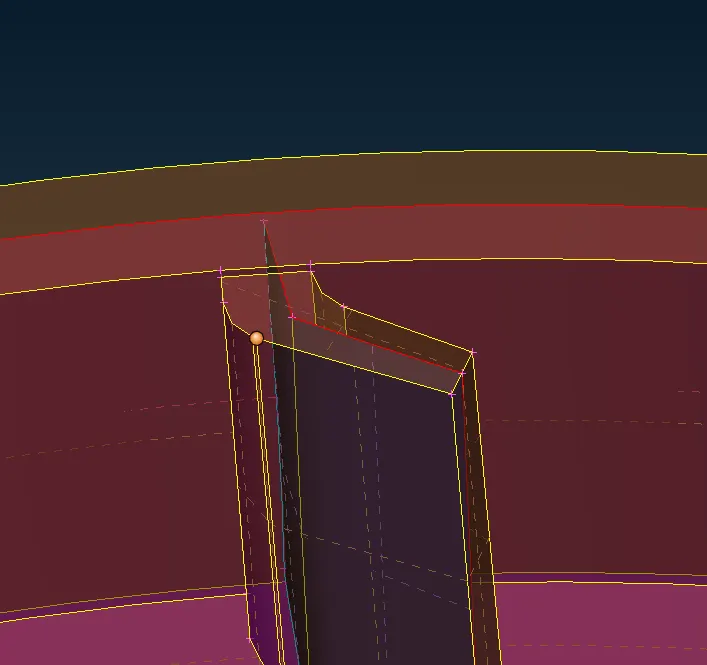
Mid-Surface of teeth
- For rotating the teeth first, we have to create the axis of rotation, for creating axis of rotation we need two different point at Centre at a different height, for that we are using COG option in point buttons, select the circle having two different heights to create a centre point at different height.
- After creating the centre points, now we can go to rotate command, here we have to define angle and no of teeth to be formed, also here we have to define the axis of rotation by selecting two centre point that we created previously.
Angle between teeth = 360 / no of teeth
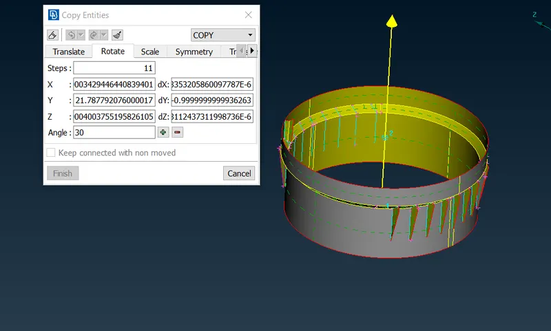
Axis of rotation
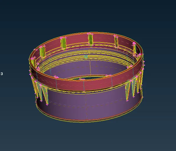

copy of lock teeth using rotate option
- Also for other teeth we are using process that we are done previously, Rotate command will help us to save significant amount of time
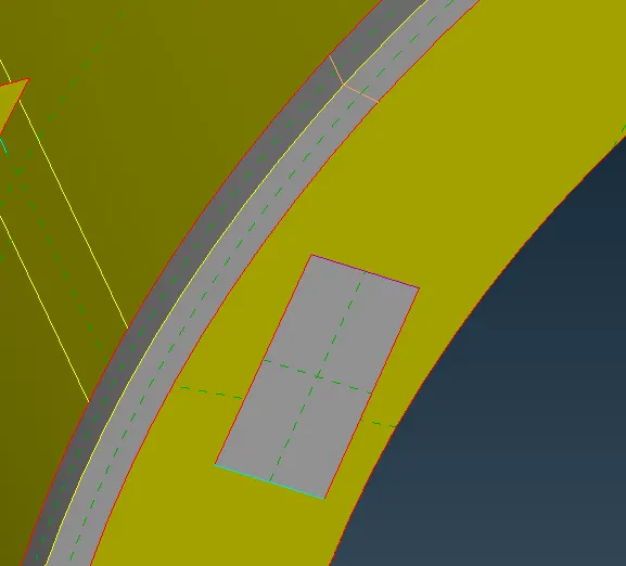
Teeth on upper part of plastic Bottle cap
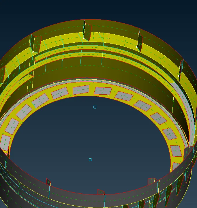
Copying of teeth using rotate command
- For complicated area like threads where thickness will vary and having trapezoidal section, it is difficult to model it in trapezoidal section because when we are giving thickness it will having a rectangular cross-section, so we have to give a average thickness to it.
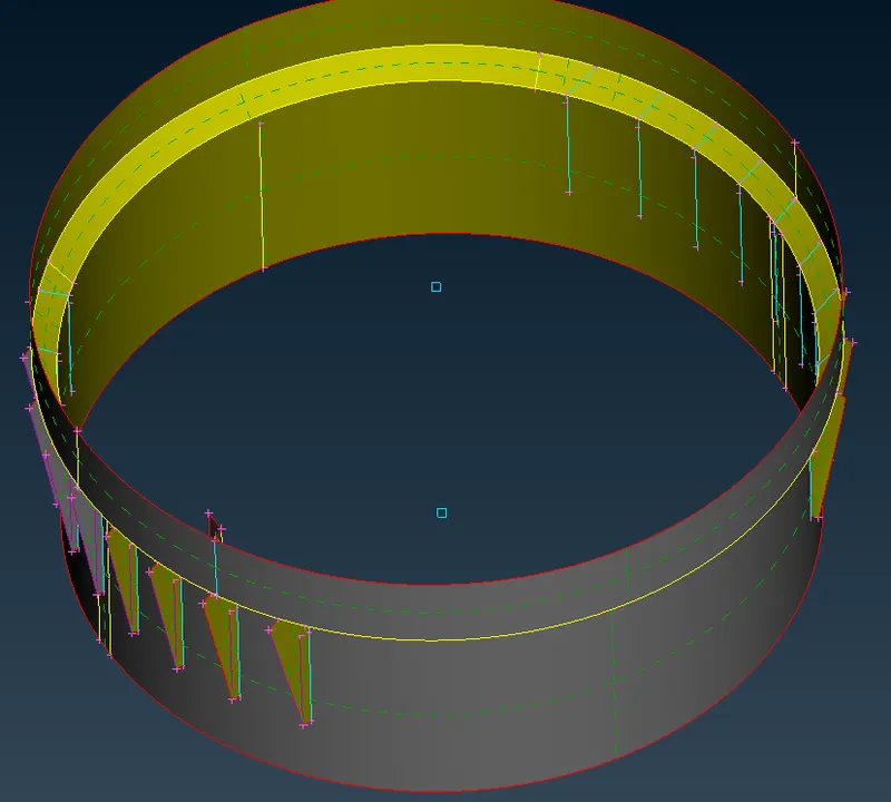
Middle surface of thread
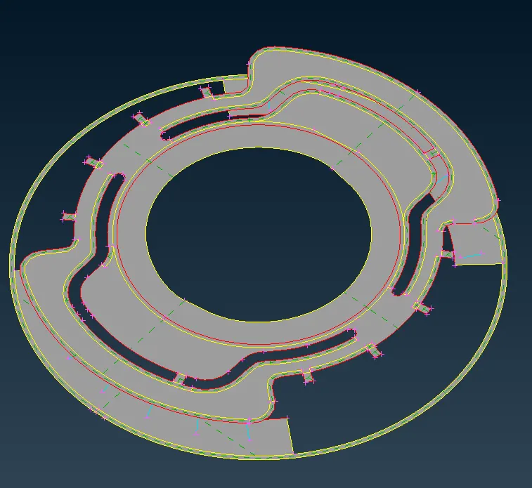
Mid-Surface of upper part of Plastic bottle cap
- once mid-surface of whole component is generated the next step is to again check for the error in the mid-surface.
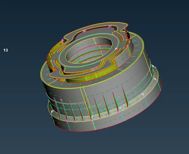
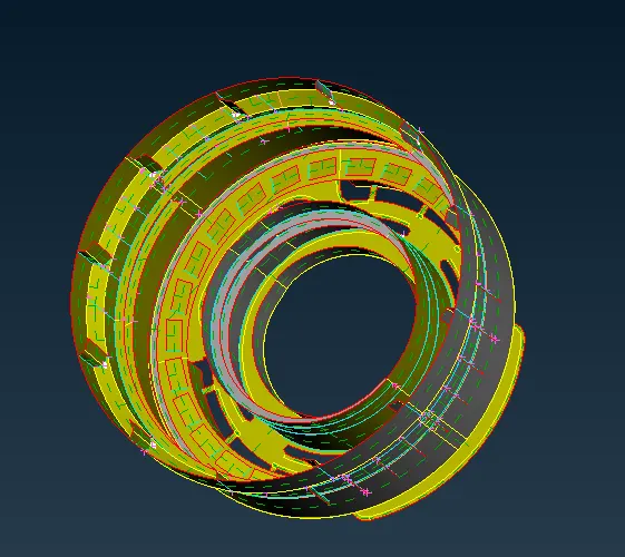
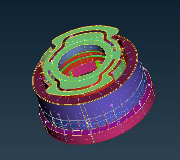
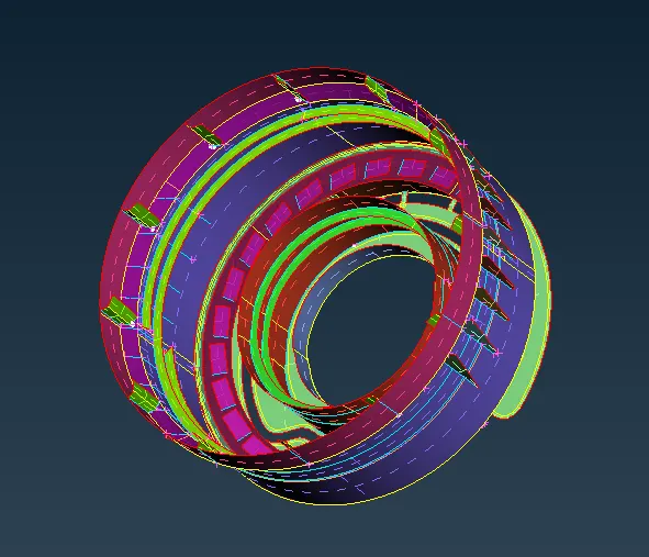
Middle-Surface of Plastic Bottle cap
- After creating the mid-surface, the next step is to create a mesh on a component, but before meshing we have to set the quality criteria and quality parameters as mentioned above
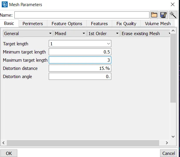
Defining a mesh parameter
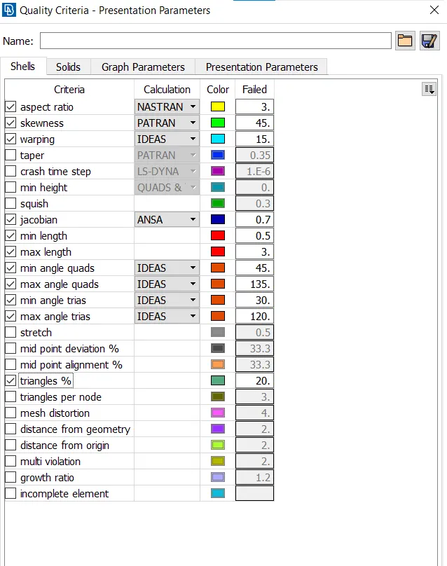
Defining a Quality Criteria
- After defining the mesh parameter and quality criteria, now we can start the mesh
- we are using best option in mesh panel to mesh the component
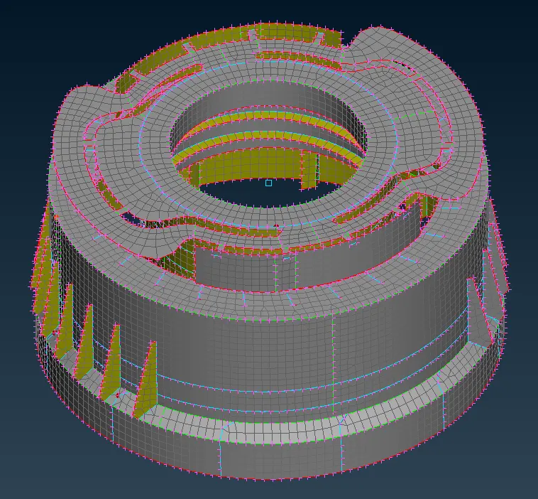
Meshed model of Plastic Bottle Cap
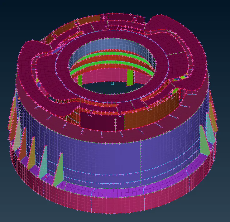
In PID mode (Different property has been assigned to different part of plastic bottle cap)
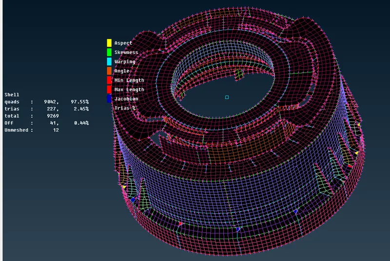
Here some of our element is failing from quality criteria because of features
- Here we previously define property to each and every part of plastic bottle cap during extraction of mid-surface of different thickness part.
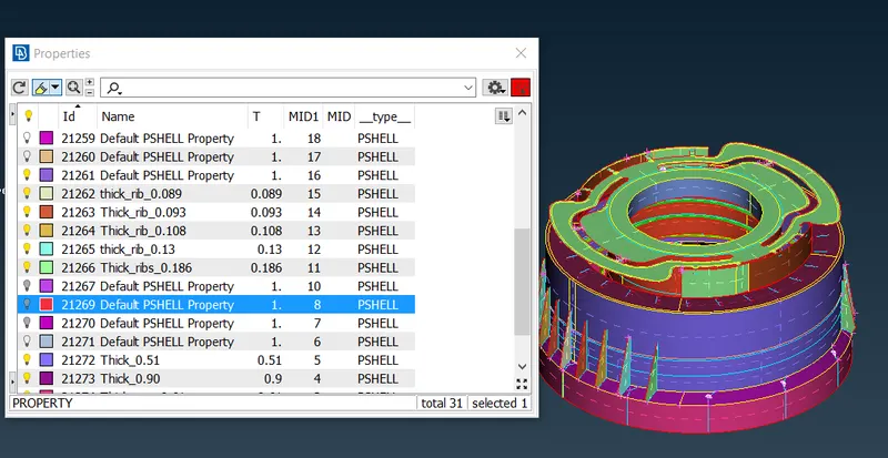
- To check whether thickness is applied properly to the component or not, for that go to quality criteria > Presentation parameter, in presentation parameter check out the shell as a solid option
- Switch on the parent geometry to check whether thickness is applied correctly or not
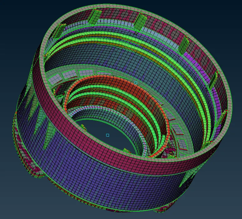
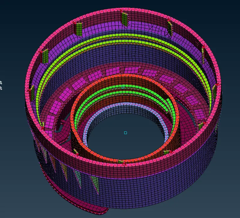
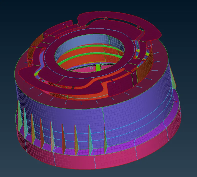
Final Meshed model of Plastic Bottle Cap
Learning Outcomes
- Understanding about manual mid-surfacing
- Understanding about plastic meshing
- Understanding about general difference between sheet metal meshing and plastic meshing
- Understanding about how to take a mid-surface in complicated regions