Week - 4 - 2D meshing for Plastic components
AIM: To perform 2D meshing for Plastic component using ANSA.
Objectives:
- Geometry clean-up
- Mid-Surface extraction and Assigning thickness
- Varying thickness of plastic component using different methods to extract mid-surface.
- Mesh creation
- Quality check
Description:
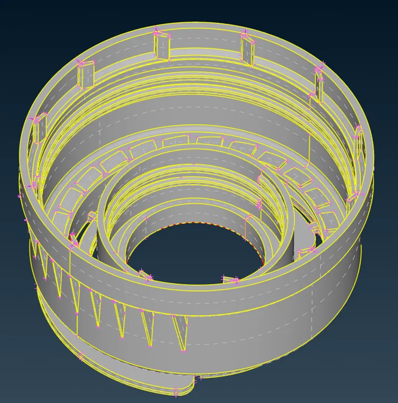
We have ANSA file as an input for this project. As we study the model, it will be very clear that it has varying cross sections, varying thickness and different features. Generally, the plastic components are made in such a way as shown in following image to improve the strength of the component and various other technical reasons.
Steps for Geometry clean-up:
- Import the CAD Geometry of Bottle Cap in ANSA software.
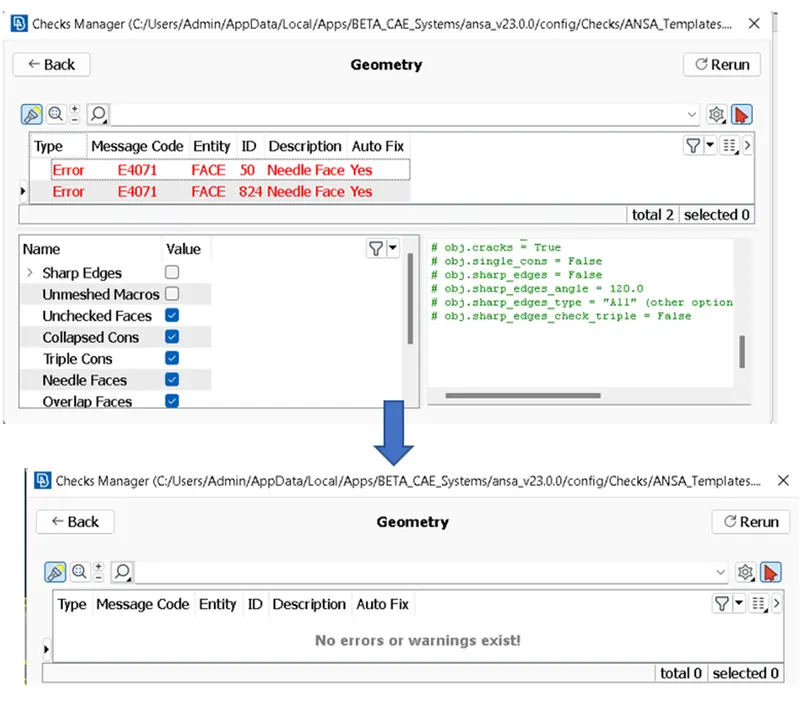
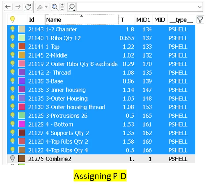
- Check out for errors and assigning the Property ID (PID).
- Do a geometry check for the model.
- ANSA detects some errors and we these must be fixed manually or by just running the automatic fix command.
- Make sure that there are no geometry errors there in the model.
Mid-Surface extraction:
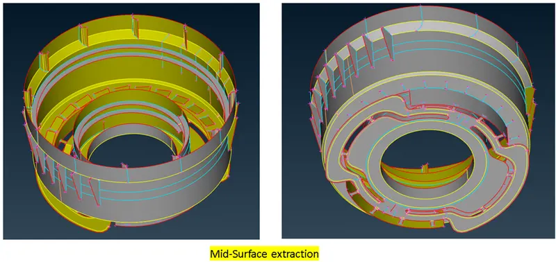
Mid surface meshing is opted for components where the geometry thickness is small when compared with the span length of the components, so if you see most of the automotive structures are of sheet metal and plastics, where the length of the component is large when compared to the thickness, hence for this reason we opt for mid surface extraction and assign the thickness of the component to the elements through properties on components method.
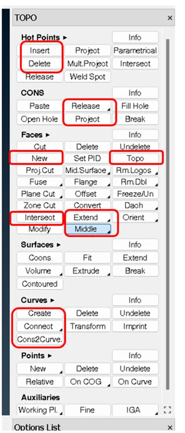
- Under the Topo module --> Faces --> we have lot of options to create the mid-surface.
- For most of the features “Offset” option was efficient. In some of areas “Middle” option was suited to extract the mid.
- In the areas where the above options were not helpful, I have used the options under “Curve “to create the curve and project option under “CONS”. A new surface was created in these complex scenarios by using option “New” under “Faces”. The below image shows the mostly used options while extracting the mid.
- For the features that were repeated, I tried to use “Transform” option to easily duplicate them and fix the CONS by extend and intersect options.
- To get the axis of rotation for the above repeated features, one can make use of COG option under “Points”.
- To extract the mid-surface in some of the most complex areas in this part, refer to the link in reference section.
Points to remember here:
- Make sure the “cross hatch” is enabled while extracting mid-surface, as it helps to select a particular region and thereby avoiding unnecessary errors.
- Think about the mesh element size while extracting mid-surface, this will let us decide whether one should modify the mid feature or keep same as parent geometry. If there are scenarios that we feel like the mesh elements are going to fail, try modify the mid-feature.
- Delete the excess hot-points that may affect the mesh flow in later stages.
- Make sure that the double and triple cons are present at the areas where they have to be because this shall affect the mesh flow in later stages.
- Switching on the transparency mode of Parent geometry enables whether the surface is aligned properly or not.
- Create a separate PID for all the mid-Surfaces extracted in the Property ID Manager in order to obtain the results at the end.
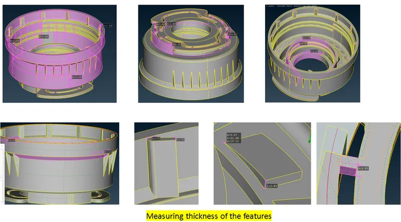
- For varying cross-sections features, I tried to take the average of the feature thickness and assigned it to make the model simpler.
- The thickness for the PIDs can be assigned now or at the later stage by measuring the parent geometry thickness as shown in following image for some features.
After creating the mid surface, check for the geometry issues and clean them up. If the issues can’t be auto-fixed, then it must be done manually. For example, if there are two edges nearby, try to remove them by suppressing (“Cut” option in Topo). Some of the triple con errors that we see can be kept as it is because of the complexity of the model.
Meshing:
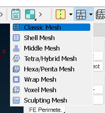
Once the geometry checks are done and fixed, “Classic Mesh” Option is selected for meshing the components.
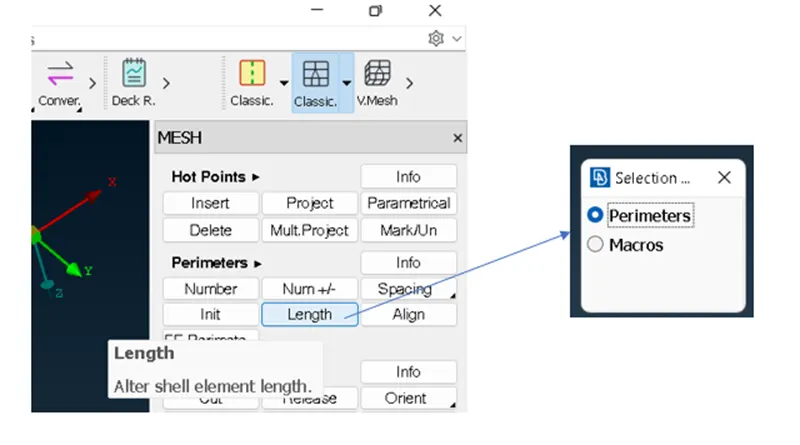
- Firstly, the length of the perimeter must be fixed by using the following option. Similarly, the macro length shall be fixed. Here, the length is taken as 1mm for both the cases. This length can be measured in the model as shown below and it can be seen that the length shall be near to 1mm.
- Mesh generation is the next step that needs to be carried out after fixing the perimeters. In this project, “Best” option is used to generate mesh for the components. For the hole/slot features, the number of nodes should be even, this can be done by using “Num +/-“ option.
- After the initial mesh is generated, one must check the quality of the mesh and for this let us define the quality criteria as shown.
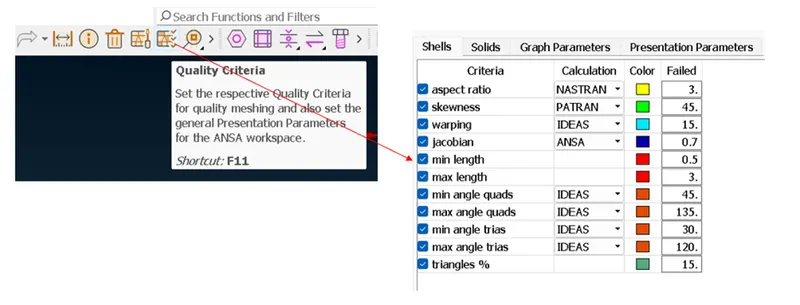
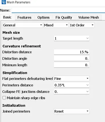
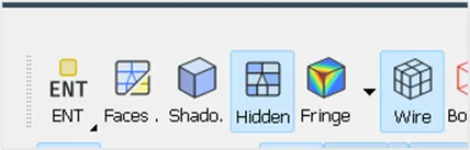
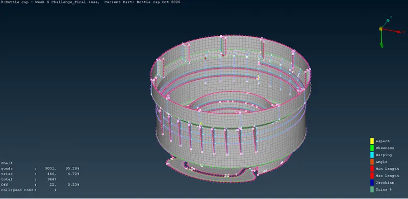
- The quality errors will be found in the mesh once the criteria are defined. These errors can be seen by switching on the hidden style. These errors can be fixed by using the options like “Improve”, “Split/Join” available in “Shell Mesh” and “Elements” section respectively. The following figure illustrated before and after the quality errors are fixed.
Topo clean-up and fixing the quality issues of the elements:
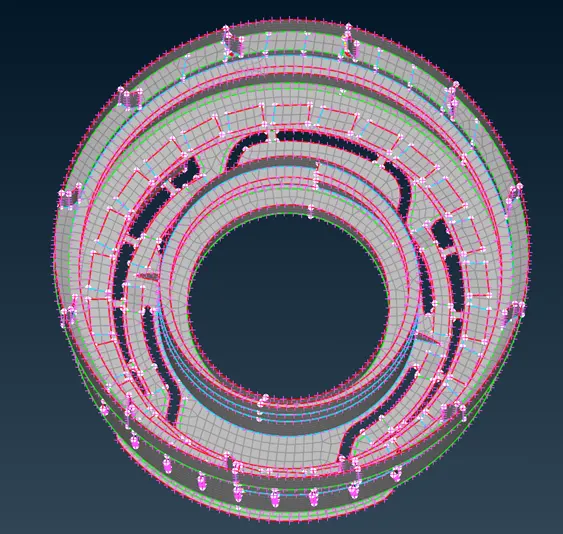
As we can notice after the initial mesh, lot of elements fail for quality. The main reason would be topology clean ups as mentioned in the above section. Remove unwanted CONS by using different options like cut, join, release, insert and delete. Once these steps are done, we can see an improvement in quality of the elements by a very number.
Other quality issues can be fixed by using “Paste” option under “Grid”, “Split/Join” option under “Elements”, “Improve” option under “Shell Mesh”.
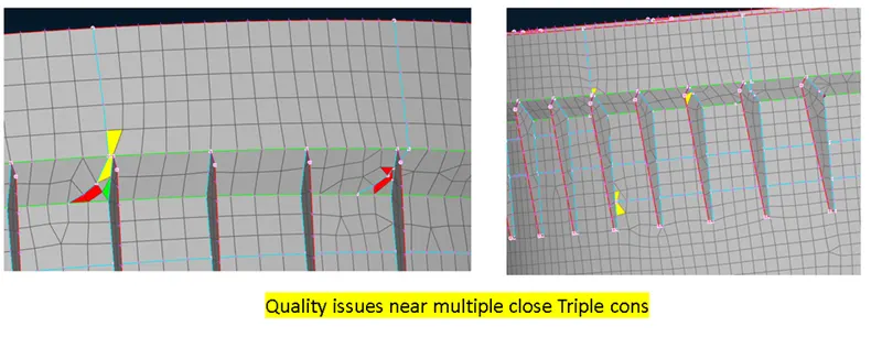
After performing all the possible operations for fixing the quality issues, we still find in some errors in the areas where the triple cons are very near to each there. These errors can be ignored for now.
Conclusion:
Thus, the 2D-meshing of a plastic component is performed and the quality issues of the mesh element were fixed.
Refer to the attached model here for more clarity.
Challenges and learnings:
- There were many challenges in initial stages, to extract the mid-surface. There were a lot of trail and error methods I have used to bring the mid to a proper stage.
- The effective usage and understanding of options under the Topo module help us to get the job done in a timely manner by not affecting the quality.
- Anticipating the mesh element fails in the mid-surface extracting stage would save us a lot of time during meshing stage as it will avoid major amount of quality errors.
References:
https://skill-lync.com/knowledgebase/how-to-extract-mid-surface-in-complicated-area