Week - 4 - 2D meshing for Plastic components
2D Meshing for Plastic Component
Aim:
For the Plastic Bottle Cap model, check for the geometrical errors and take the mid surface using suitable mid surfacing techniques. PID and Thickness assignment has to be done for all the mid surfaces. Mesh the same with the given element Quality criteria.
Given:
|
S.No |
Quality Criteria |
Value |
|
1 |
Target/Average length |
1 |
|
2 |
Minimum Length |
0.5 |
|
3 |
Maximum Length |
3 |
|
4 |
Aspect |
3 |
|
5 |
Warpage |
15 |
|
6 |
Skewness |
45 |
|
7 |
Jacobian |
0.7 |
|
8 |
Minimum Quad Angle |
45 |
|
9 |
Maximum Quad Angle |
135 |
|
10 |
Minimum Tria Angle |
30 |
|
11 |
Maximum Tria Angle |
120 |
|
10 |
Tria Percentage |
15 |
Procedure:
- Importing the model is the first step. For this we click on File > Open > Select the file (.igs , .step , etc.) > hit Open.
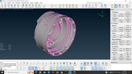
- We will perform basic operations before meshing, ing i.e. Cons resolution, Geometry check, topo if any surfaces are not joined properly, and orientation.
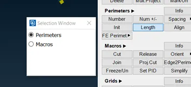
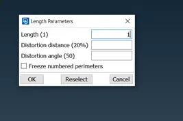
- For cons resolution Mesh Module > Perimeters > select whole model with left click and dragging > hit middle mouse > put length as 1 > hit Ok.
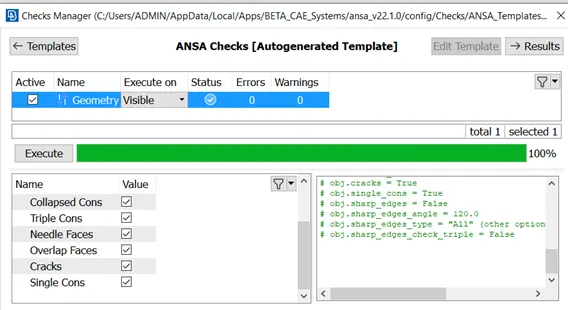
- Now for geometry check go to tools > checks > Geometry > Execute > if find any errors fix them by right click and Fix option.
- Now for extraction and meshing we are going to use the casting option which obtains FE.
- Fill out all the quality criteria and mesh parameters given.
- For casting go to topo module > Faces > Mid.surface > Casting. In casting put the minimum thickness of the model and target element size as given also uncheck the option ‘stop at geometry errors’.
- After hitting it will take some time to process and give the FE of the model.
- Now turn off the macros the FE will appear.
- In some parts it will be good mid-surface with meshing sometimes we get disturbed FE.
- To correct those areas we are going to use Align manager present in the midsurafce option.
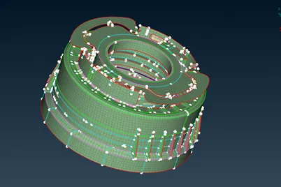
Casting Result
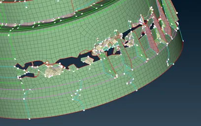
Disturbed areas after casting
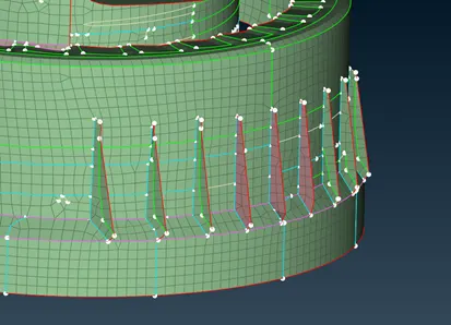
Good areas after casting
- There will be many approaches to correct the areas sometimes you with the definitions of areas sometimes you try to correct perimeters or you try to join them.
- First we will learn how to use Align Manager.
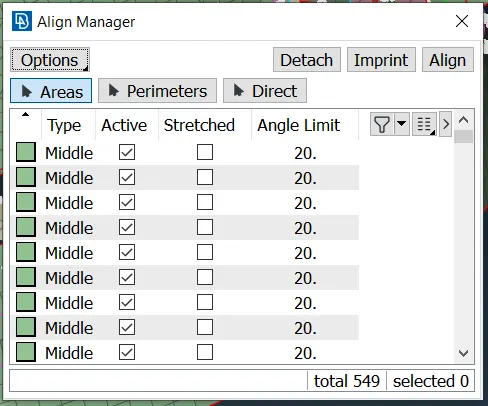
- Image above is a pop-up of align manager is consist of Areas, Perimeters, and Direct. Also, other options like Detach, Imprint and Align are present.
- We mostly deal with Areas and Perimeters in correcting FE areas. Areas Consist of three definitions Middle, Plane & Empty.
- Middle is the Definition for curve surfaces, the plane for the flat surfaces, and Empty means there is no definition for FE.
- In perimeters Sharp is for edges, triple is for triple cons, offset is for double con and faces is for free edge single con.
- Also sometimes it’s difficult to correct areas with align manager and other operations. We delete the complicated areas and fill them using the fill option present in the mesh module > shell mesh > Fill. And will provide a definition to align with the surface.
- After correcting FE areas we look for the mesh flow. Using different options like Split, Paste, Join and Swap we deal with trias. Try to use smooth after using these options.
- For better results of mesh use Improve option in shell mesh. Also for quality criteria try to Smooth mesh to obtain quality mesh.
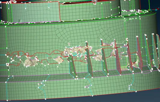
FE created by Casting
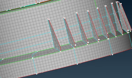
Corrected FE with better mesh flow
- FE for threads in a bottle cap is not proper in casting so we will do it manually. For that, we will first delete all the FE related to threads.
- Now we will create a curve using the Middle option in Topo Module > Curves > Middle. Hit middle selects one edge middle mouse click then select the second edge again press middle mouse click.
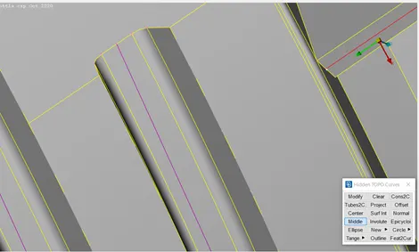
- Now fine that curve to get proper. Now project it on FE and then fill it using Fill Option in the mesh module.
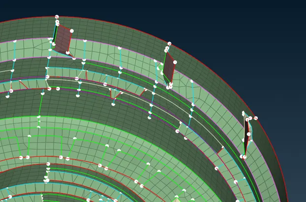
Threads created by Casting
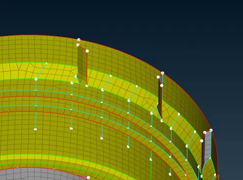
Threads created manually
- For teeth we will do the same operation for creating single teeth. And Use Transform > copy and use Rotate.
- Final step is to assign thickness using the option convert for that go to mesh module > Grid > Thickness > Convert, keep it Nodal to Property and thickness step as 0.1. This is how we need to deal with bottle cap meshing.
Results:
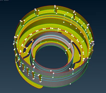
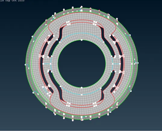
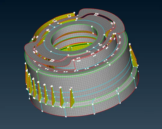
Learning Outcomes:
- How to Casting option In ANSA.
- Learned how to use Align Manager.
- Auto midsurfacing in ANSA.
- How to deal with disturbed FE using different tools and approaches.
- Use of transform option in copy and rotation.
Conclusion:
For the Plastic Bottle Cap model, we checked for the geometrical errors and take the mid surface using Casting auto mid surfacing techniques. PID and Thickness assignment has to be done for all the mid surfaces. Meshed with the given element Quality criteria.