Week - 4 - 2D meshing for Plastic components
Aim:- To extract the midsurface and perform geometry cleanup for the given plastic bottle cap model and mesh the same with given element quality criteria as mentioed below and assign a proper thickness to it.
Objective:-
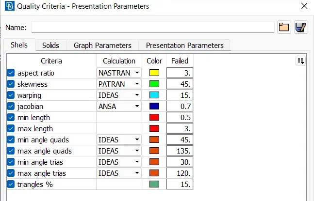
* All the 2D elements should clear the given quality criteria except near to Triple CONS or at smaller regions.
|
S.No |
Quality Criteria |
Value |
|
1 |
Target/Average length |
1 |
|
2 |
Minimum Length |
0.5 |
|
3 |
Maximum Length |
3 |
|
4 |
Aspect |
3 |
|
5 |
Warpage |
15 |
|
6 |
Skewness |
45 |
|
7 |
Jacobian |
0.7 |
|
8 |
Minimum Quad Angle |
45 |
|
9 |
Maximum Quad Angle |
135 |
|
10 |
Minimum Tria Angle |
30 |
|
11 |
Maximum Tria Angle |
120 |
|
10 |
Tria Percentage |
15 |
* Extract the mid surface of given plastic model accurately.
* Featured are captured properly with good mesh flow in model.
* Assign the proper thickness to the midsurfacfe of all components.
Procedure:-
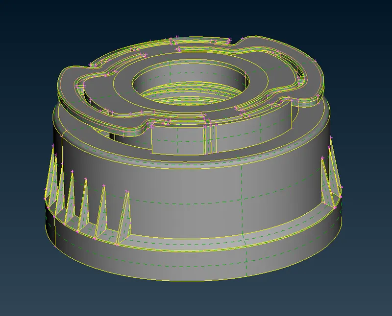
* Import the given model :
* First we import the model in ANSA ( file - open - select file - ok )
* Check the Geometry :
* For check the geometry we check one by one all components separately. ( tools - checks - geometry )
* If erros are shown in check manager we have to fix it.
* Some errors are clear by ansa and some which can not clear by ansa that errors are cleared manually.
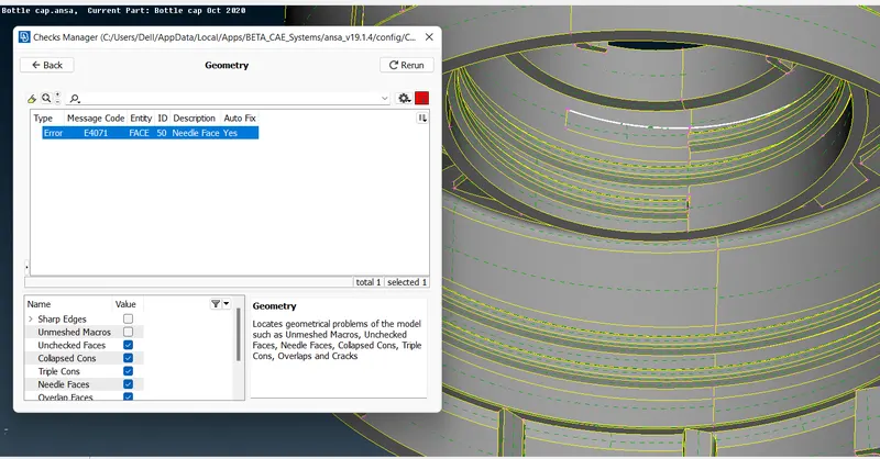
In this model we found 1 error which is fix by ANSA.
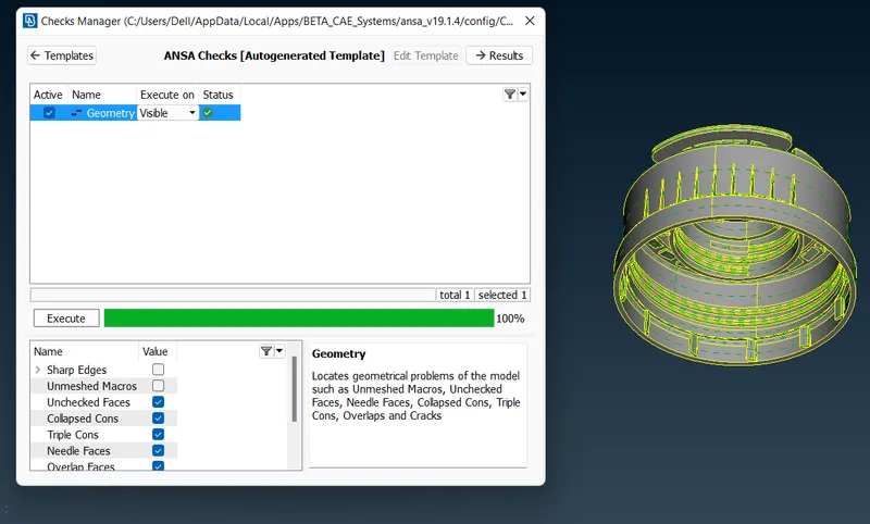
In this way we check our geometry and clear the issues.
* After that, we can go ahead and change the cons resolution by accessing the mesh module and selecting 'length' in the perimeter section. We will then need to select the whole model and assign a 1 mm length. This improves the resolution of the model
* Extraction of Mid surface :
* For mid surface first we check the component and its thickness. for this we use measure commant. ( utility - measure)
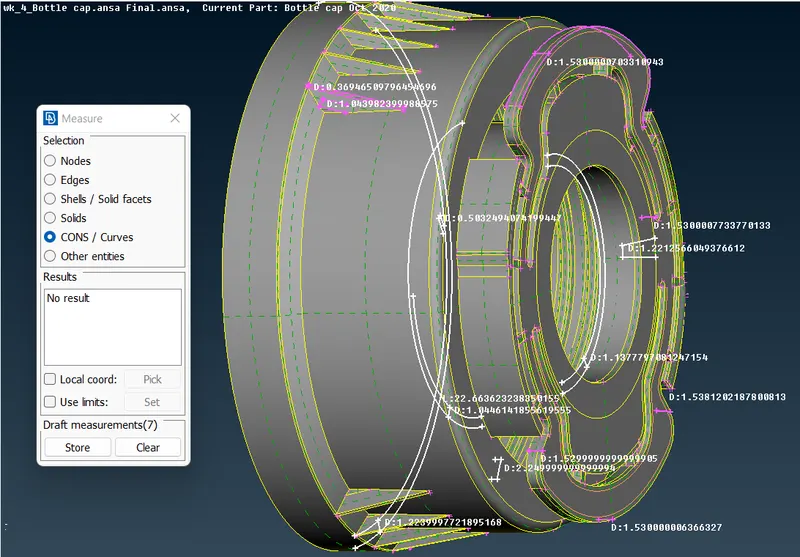
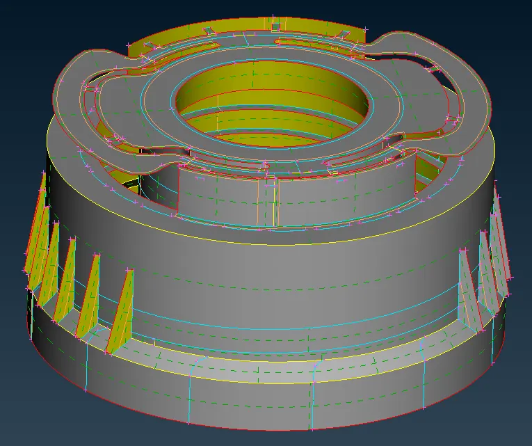
* The given model is plastic component so it have non uniform thicknesses throught the component we can in above image.
* Given model is plastic component and have non uniform thickness , we use manual method for extraction of mid surface for this model.
* For extraction of mid surface we use different- different tools and approaches.
- we use offset tool for extraction of mid surface for those surface whic are uniform and plane in any one of it's side.
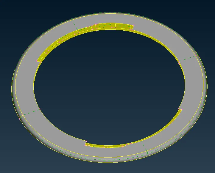
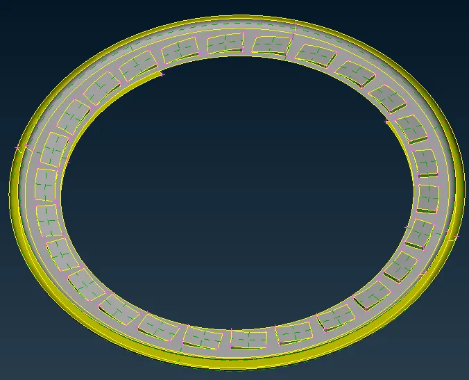
* As we can see that is above images 1 side of surface is plane and other one is having teeths so in this type of surfaces we use offset option.( topo - facea - offset )
- We use middle tool for extraction of mid surface for those surface which are uniform in both the sides. its very fast tool.( topo - facea - middle)
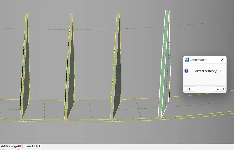
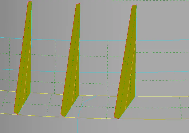
* in above image we can see that how easily we extract the mid surface for this ribs type of surface which have uniform surface both side.
- We use Curve middle tool for extraction of mid surface such as threads and ribs of small surfaces. ( topo - curves - middle)
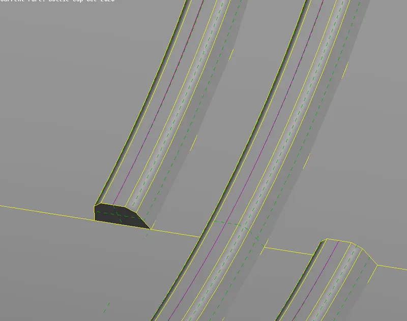
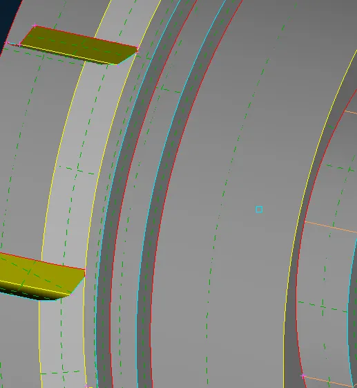
* After the creation of middle curve we project this curve to base mid surface and create the new surface and in this way we get mid surface of such complicate surfaces. ( topo - cons - project ) ( topo - faces - new - cons)
* We use faces offset tool for extracting mid surface of teeths. After this we extent this surface to the base mid surface .( topo - facea - middle),.( topo - facea - extend)
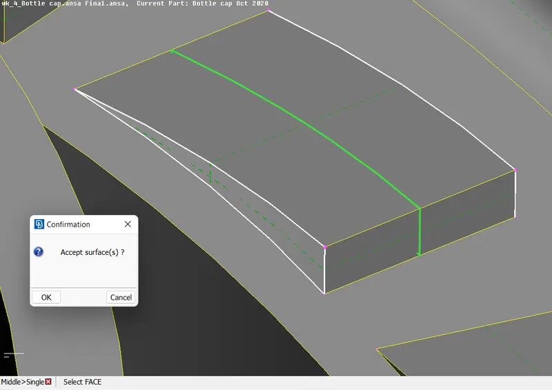
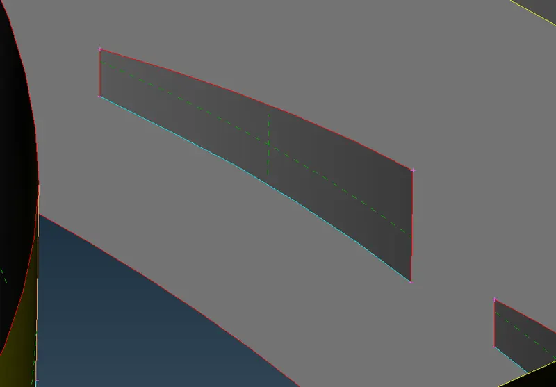
* As we can see in above image we take a midsurface of one teeth and then for others teeth we use translate tool and rotate the extracted teeth mis surface for all the teeths.
* For translate we the mid surface of teeth we have to create 2 COG points , and rotate the surface with these 2 cog points. for rotation we heve to gine angle = 360/ no of teeths. ( topo - points - on COG - edges ( select circle ) ) , ( translate - rotate )
* for those surfaces which are not connect with base mid we use extend tool and also we use intersect tool for creating T-connections.
* In this way we extract the mid surface for whole component separately.
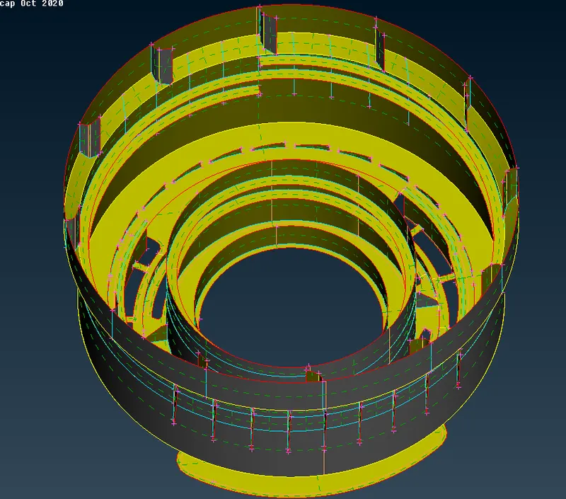
* After extracting the mid surface for whole component we have to check the mid surface through camparing with parent geometry. for this we use transperancy option , we go to property and on transperancy of parnet model property and compare it with newly generated mid surface.
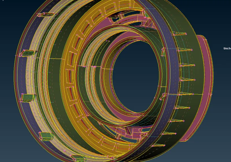
* Create property and assign thickness :
* After taking the midsurface of all the surfaces we have to create separate property for each mid surface and assign the proper thickness according to the parent model thickness.
( Faces - setPID - select the entity and create the new id - Pshell - mention thickness - ok)
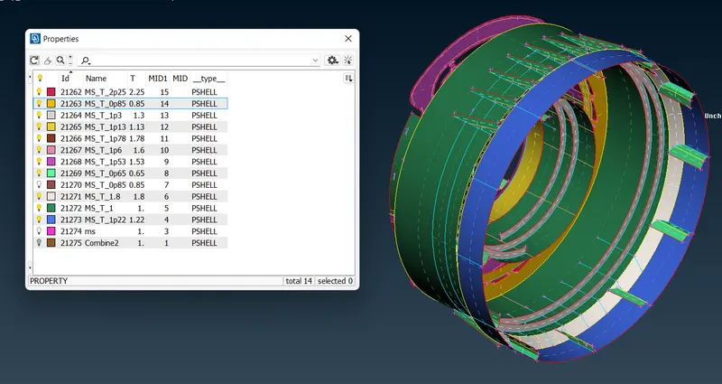
* As we can see that in above image , we segregate the surfacfe in different - different PID's according to thicknesses.
* Mesh Generation with quality parameters :
* First of all we set the orient for the model so that our elements are in same face/normal.
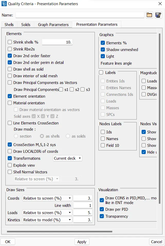
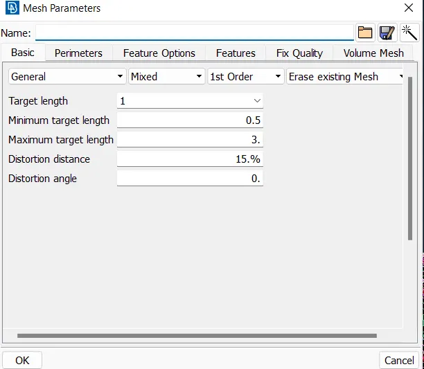
* Before start meshing we have to set the given quality criteria and mesh parameter as shown in below image.
- 2D mesh generation :
* We mesh all the component one by one.
* First we set the perimeter length as 5 , according to the target length for all the components.
( mesh - perimeter - length - target element size)
- Check the geometry and do appropriate topology cleanup.
* we check the geometry where element are failed for minumum length and then we take appropriate action such as toggling the cons.
( Mesh generation - best mesh - select surface - mesh)
* For generating the better mesh flow we have to avoid the Trias at the basis on -
Avoid the trias which are forming opposite to each other.
Avoid the trias,near fillet regions.
Avoid the trias,near the circular holes.
Avoid the trias,edges of the geometry.
Avoid the trias,back to back trias.
Which will effect the results of the model and these can handled by some tools such as split(use in multiple ways are spilt,swap,join and dividing the quads),paste(use in movement of backward direction of trias).
* We use reconstruct tool to clear trias and get better mesh flow.
* we use split element tool to get rid from tria elemetns and opposite trias.
* we use smooth option for better arrangements of elements.
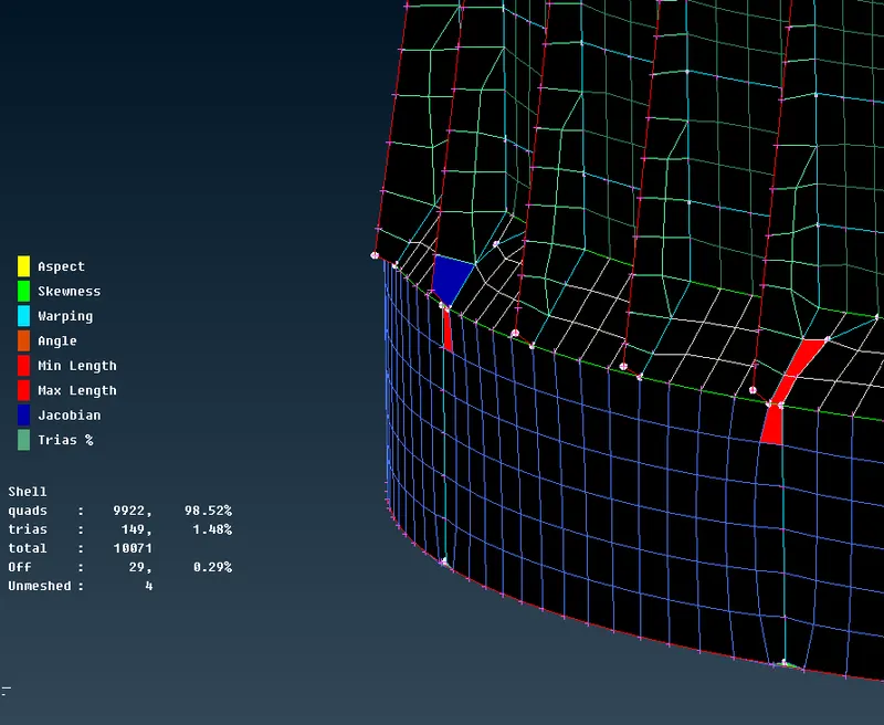
* We use Hidden mode of drowing style to see the quality of elements.
* We use Move tool for clear the element quality.
* We use paste tool for remove the tria elements.
* This above process is used for all the surfaces for meshing and clearing the quality criteria of elements.
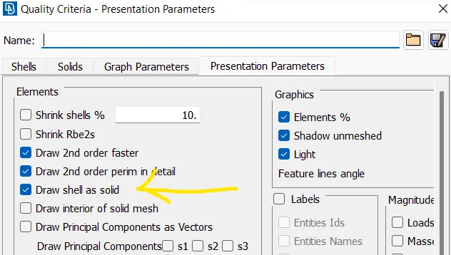
* In order to see the thickness of the component go to the utility - quality - on the draw shell as a solid - on and in the below image we can see the thickness of the component.
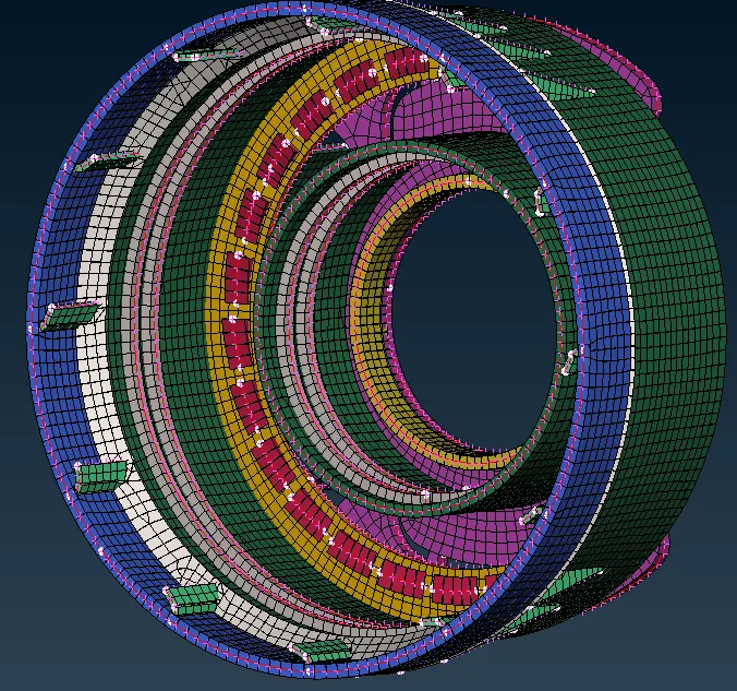
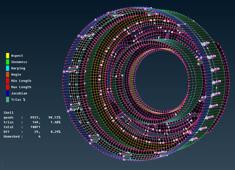
* complete meshed model.
* IN entity mode
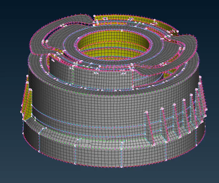
* IN PID mode
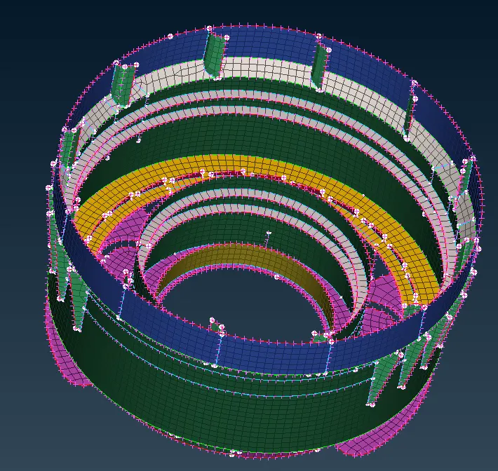
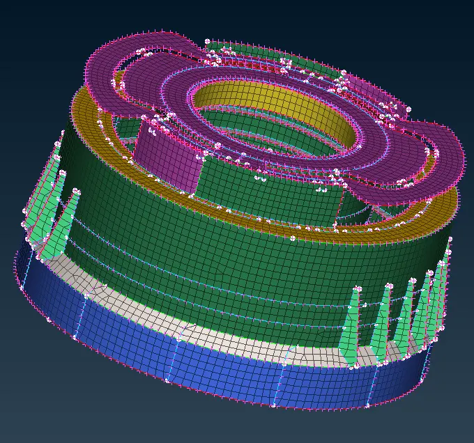
* IN entity+hidden mode
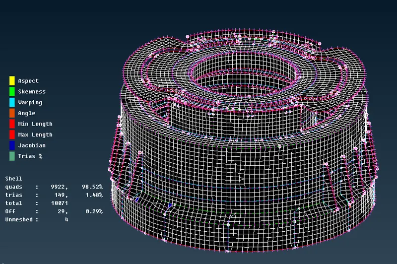
* IN PID+hidden mode
Learning Outcomes:-
* Understood about extracting mid surface of plastic components.
* Learn how to extract mid surface of complicated surface such as tooths and threads and ribs.
* Understood how to assign thickness to plastic component and set PID's.
* Learn different tools and techniques for clearing the quality of elements and improven mesh flow throught the whole component.
Result :- The mesh is obtained significantly on given model with required quality criteria.
Conclusion:-
Learn differernt tools and techniques and understood how to mesh plastic component. the given model successfully meshed with proper thickness assining.