Week - 4 - 2D meshing for Plastic components
OBJECTIVE :
To clear all the geometrical errors in the given Bottle cap component and extract midsurface with suitable technique followed by 2D shell meshing with given quality criteria.
|
S.No |
Quality Criteria |
Value |
|
1 |
Target/Average length |
1 |
|
2 |
Minimum Length |
0.5 |
|
3 |
Maximum Length |
3 |
|
4 |
Aspect |
3 |
|
5 |
Warpage |
15 |
|
6 |
Skewness |
45 |
|
7 |
Jacobian |
0.7 |
|
8 |
Minimum Quad Angle |
45 |
|
9 |
Maximum Quad Angle |
135 |
|
10 |
Minimum Tria Angle |
30 |
|
11 |
Maximum Tria Angle |
120 |
|
10 |
Tria Percentage |
15 |
PROCEDURE :
1. The given CAD component of bottle cap is a plastic component which directly means that the component would have different thickness throughout its span. In this case, only manual midsurfacing using Face >> Offset would be the most desirable method to extract the midsurface.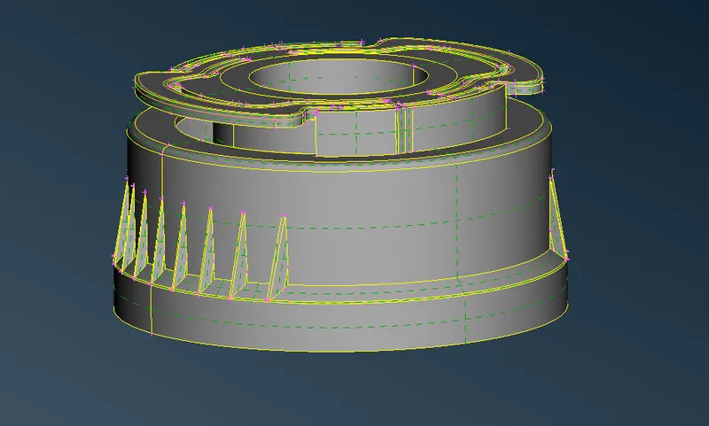
2. For our convenience, the parent geometry can be divided into two parts like upper and lower part such that it would be easier to capture the midsurface and perform meshing with proper mesh flow. Now, once the model has been seperated into two parts, Perimeters and macros are set to target element length which is 1mm such that all the features can be viewed in good resolution. Mesh >> Perimeter >> Length = 1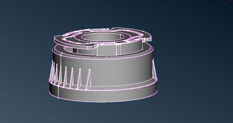
3. Now the geometry has to be checked for any missing surface, errors etc to be fixed. Go to tool bar >> Checks >> Geometry >> Execute.
If there are any errors in the parent geometry, most of the errors can be fixed with the auto fix algorithm such that the geometry would finally become free from any errors.
4. Then, the midsurface has to be extracted for each and every part which is seperated. Go to Topo >> Faces >> Offset and select the entity and provide the thickness value. In case if the part has varying thickness throughout the span, average thickness can be given to get the midsurface properly.
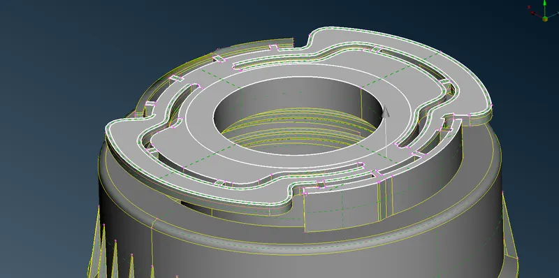
5. For certain special features like the ribs present in the outerside, the midsurface can be extracted by using Faces >> Middle >> Single >> select the entitiy and click middle mouse button. Then the midsurface can be extracted for the ribs present in the outer side. Similarly, the ribs which are present in the inner side is of more in number. In order to reduce the effort and save time, one of the middlesurface can be copied and transformed to the other parts as well. Firstly, the cons which is attached to the base has to be projected and then using curves we should create a middle curve which gives an outline for middle of the rib. Now, using those two, we can create a new face and the transform the rest.
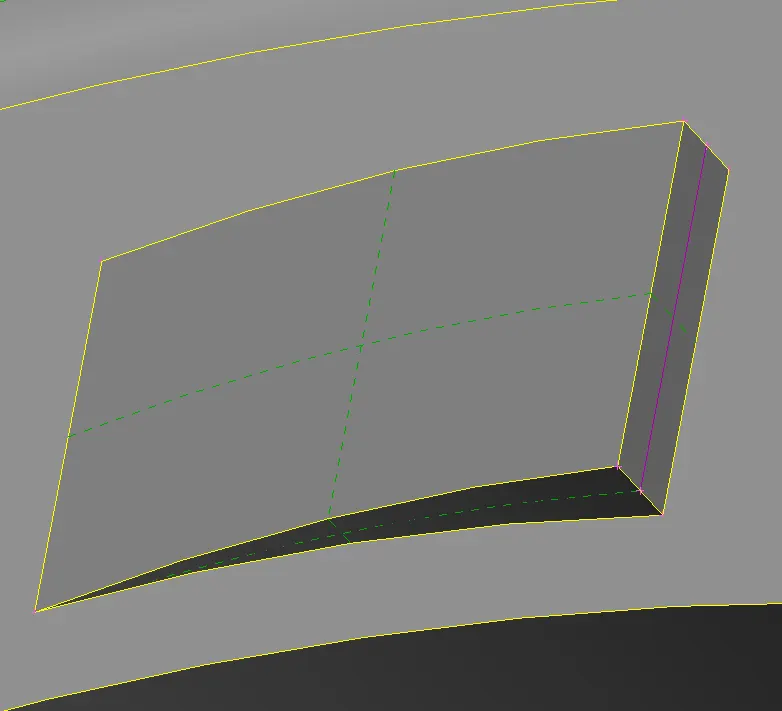
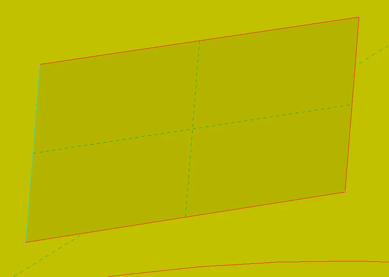
To copy the rest, go to Transform >> select entity >> Rotate >> Steps ( no of copies excluding the source ) >> COG points ( to be created as axis of rotation from Points ) >> Angle ( 360/no.of.ribs)
Following these would create the ribs of required numbers.
6. Now, to capture the thread inside, it is not easy to capture the trapezium shaped threads, so we can create a curve which acts a middle part of the whole thread and then project the curve to the surface, then we can create new face by using those projected cons and the curves to create the thread.
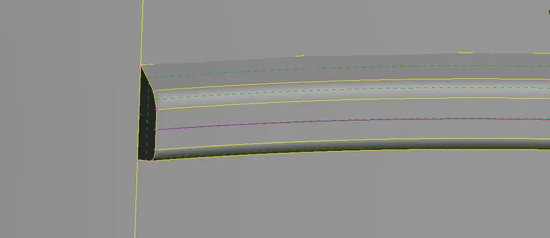
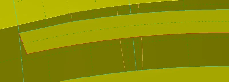
7. Other midsurface can be extracted by usual face >> offset method and the face >> Middle method, Once all the midsurface has been extracted, the middle surface needs to be checked for any geometrical errors. For this go to tool bar >> checks >> geometry >> execute (unselect single cons for middle surface ) and fix the errors if any.
8. Now, go to Faces >> set PID >> New >> PSHELL >> Enter desired thickness >> apply for the respective surface to provide thickness for the component
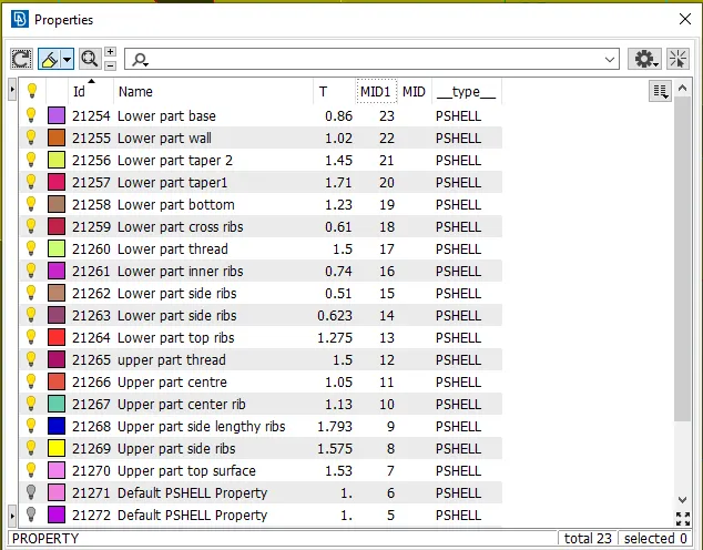
9. Now, set the mesh parameters and quality criteria with the given data and then perform meshing in all areas. For better mesh flow, the surface can be cut into smaller areas and then it can be joined once the meshing is done. While cutting the faces, the mesh type should be changed to keep such that while editing the faces it won't disturb the mesh which is already present on the faces.
10. After meshing, go to Quality criteria and presentation parameters > Check the draw shell as solid to represent all the shell elements created with the provided thickness value. After then, all the elements should be checked for any free edges, If there are any the nodes of those elements should be manually pasted. Grids >> Paste >> Select the nodes >> Middle mouse button.
RESULT :
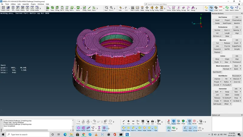
Thus the given plastic component has been meshed successfully with 2D shell elements by following all the quality criteria.
INFERENCE :
From this challenge, creating midsurface for the threads using the curves was learnt. Also usage of transform and rotation of the midsurface to replicate the midsurface along an angle was learnt. Apart from these, midsurfacing for varying thickness component using the faces >> Middle option was learnt with all other usual techniques.