Week - 4 - 2D meshing for Plastic components
OBJECTIVE: To check for the geometrical errors for the given Plastic Bottle Cap model and taking the mid surface by suitable mid surfacing techniques. Assigning PID and thickness for all the mid surfaces. Meshing the same with the below-given element Quality criteria.
|
S.No |
Quality Criteria |
Value |
|
1 |
Target/Average length |
1 |
|
2 |
Minimum Length |
0.5 |
|
3 |
Maximum Length |
3 |
|
4 |
Aspect |
3 |
|
5 |
Warpage |
15 |
|
6 |
Skewness |
45 |
|
7 |
Jacobian |
0.7 |
|
8 |
Minimum Quad Angle |
45 |
|
9 |
Maximum Quad Angle |
135 |
|
10 |
Minimum Tria Angle |
30 |
|
11 |
Maximum Tria Angle |
120 |
|
10 |
Tria Percentage |
15 |
PROCEDURE: a) Import Geometry, give perimeter length as 1 unit for geometry resolution, give topo for the geometry, and perform geometry check-up and fix all the issues.
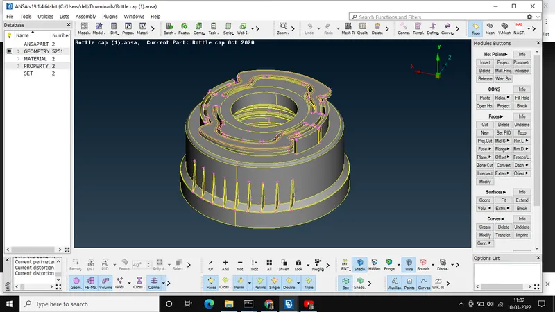
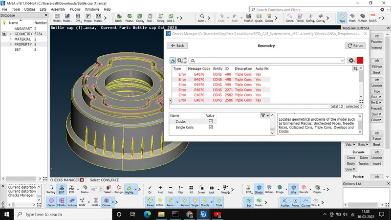
Geometry before and after geometry clean-up.
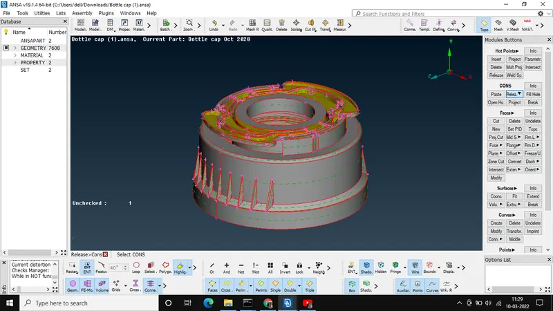
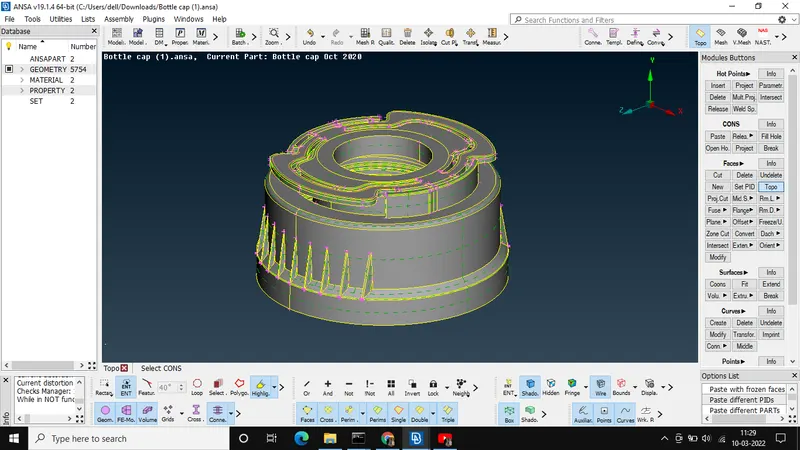
b) Checking thickness and offsetting the surfaces from the side which has very minimum features
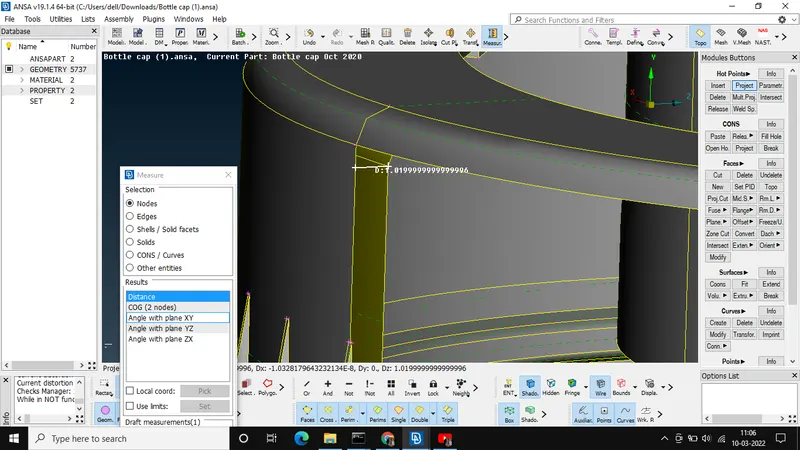
c) For surfaces having variable thickness we can extract the mid curve and create a new surface.
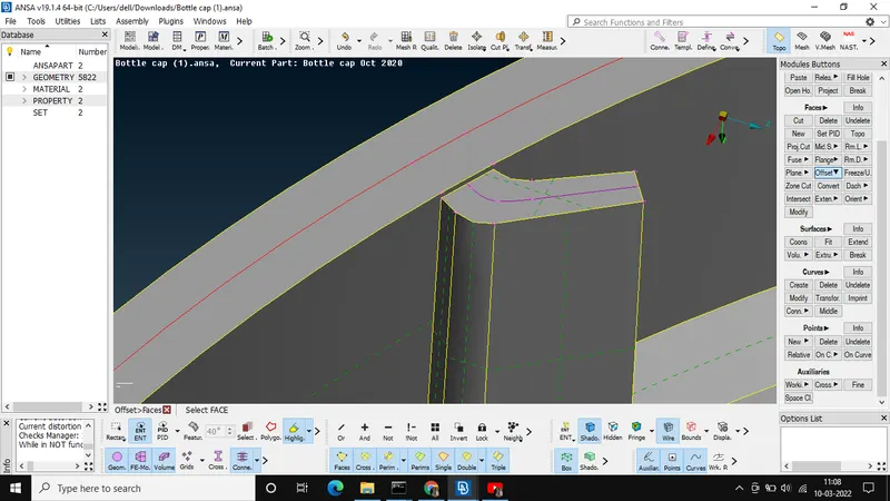
Midsufaces for the threads can be extracted in a same way.
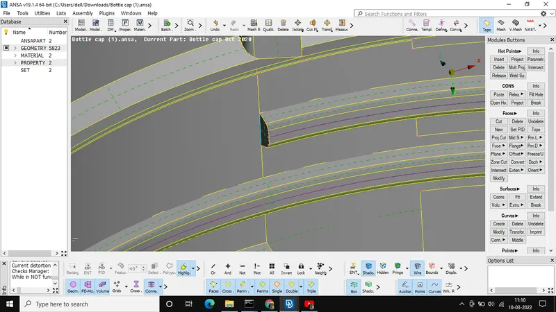
d) Mid surfaces for the bottle cap are extracted.
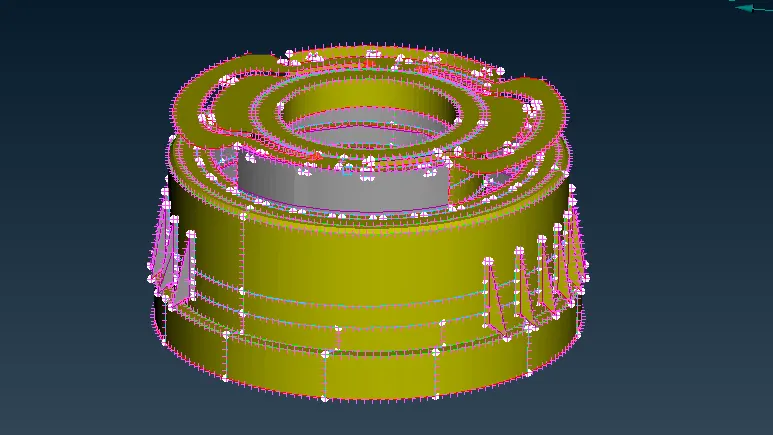
c) Before meshing giving all the mesh parameters and element quality parameters.
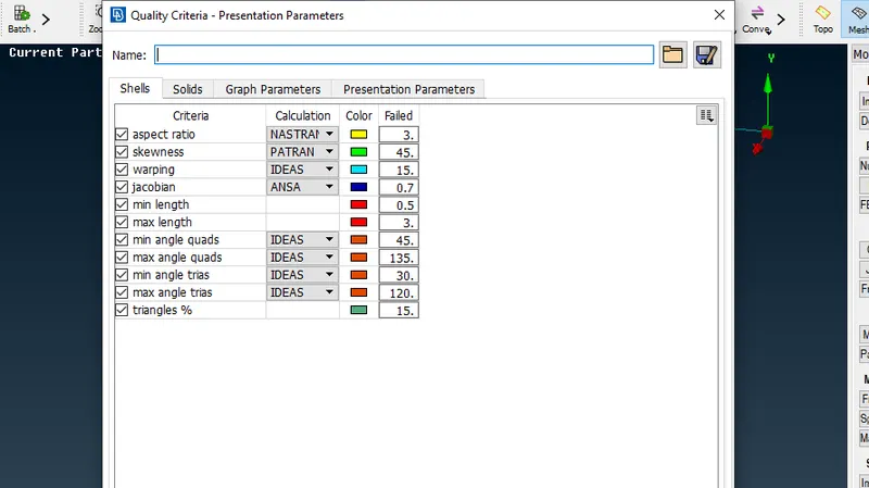
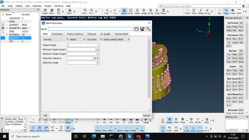
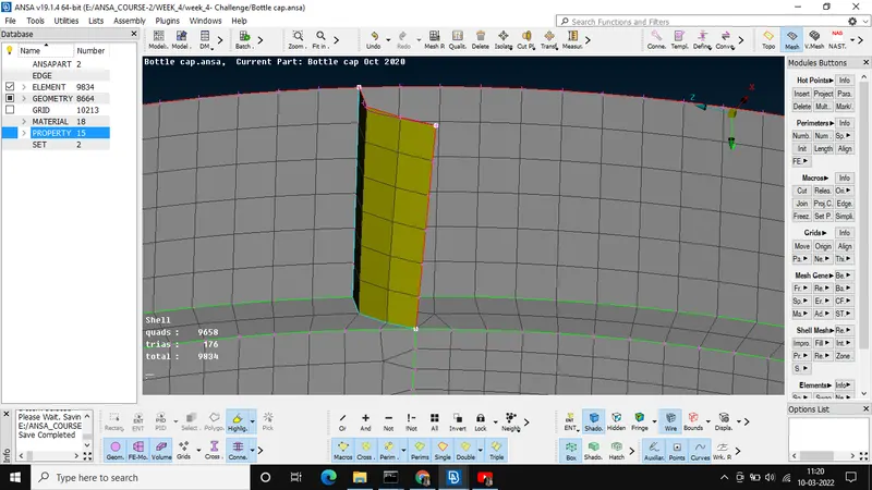
d) Meshing the surfaces one by one by giving necessary cuts.
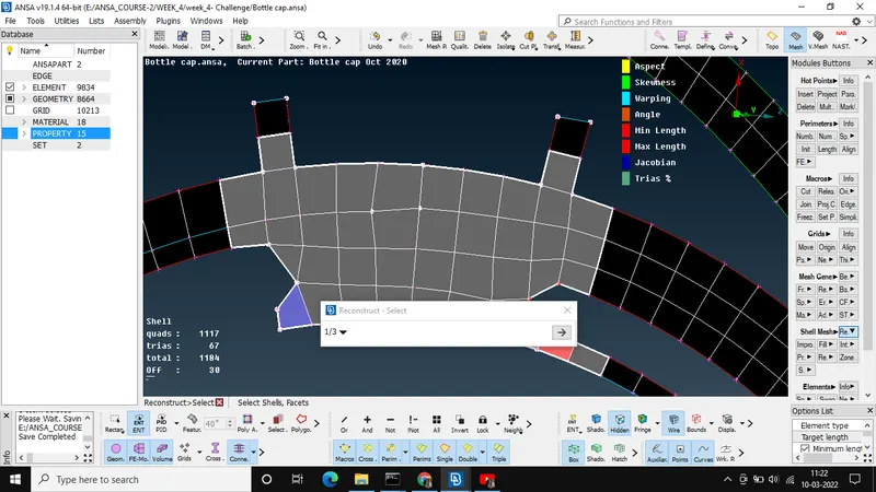
e) Checking the off elements and editing them by using reconstruct, smooth align options.
f) Now creating New PID for all the elements having a similar thickness.
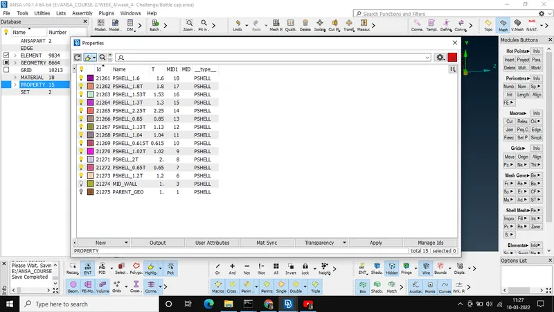
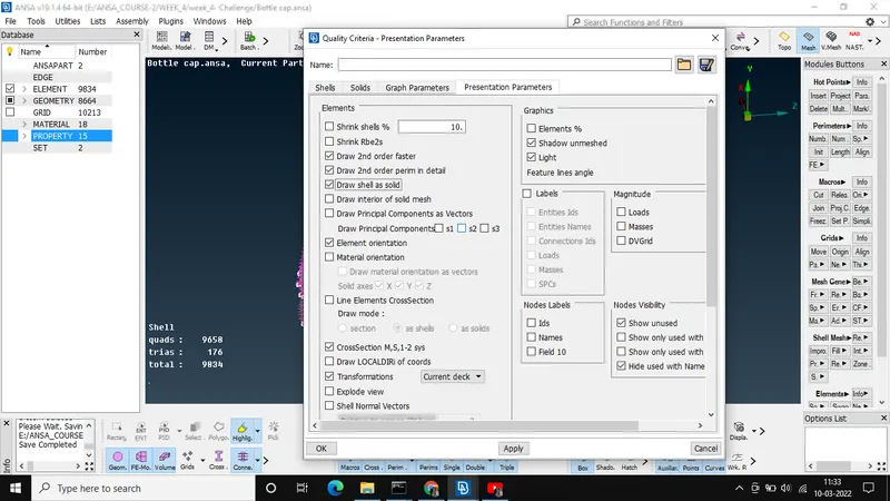
f) Now after assigning thickness to all the components to view the 3D elements we need to go to quality criteria and presentation parameters and tick the
"Draw shell as solid".
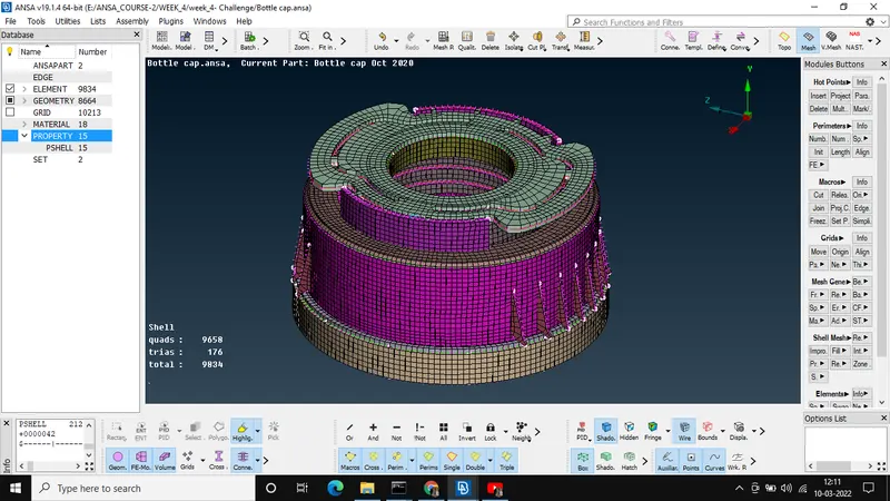
FE MODEL before and after applying thickness
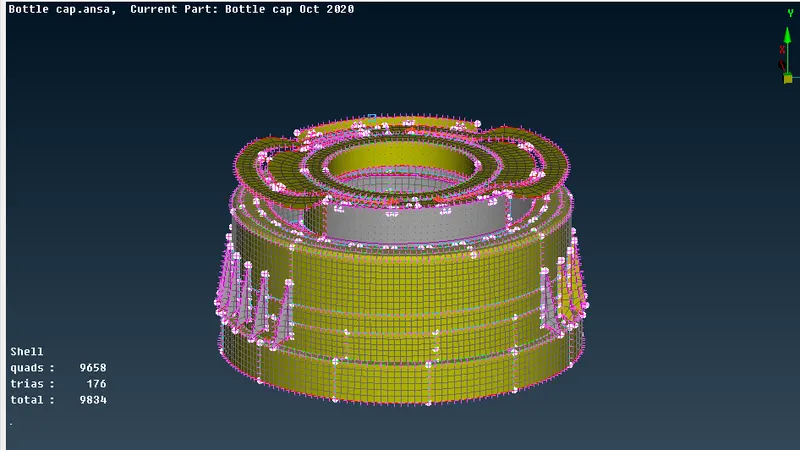
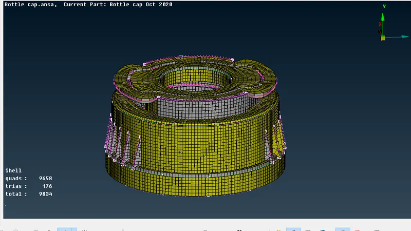
FINAL FE MODEL
OUTCOMES: Learnt how to offset surfaces of components having varying thickness.
Learnt how to set PID for components of varying thickness.
CONCLUSION: It is important to set a new PID for components having different thicknesses.