Week - 4 - 2D meshing for Plastic components
AIM:
To perform geometry clean up and shell mesh the given model of a bottle cap with given quality criteria.
Methodology:
The methodology for the given element is as follows:
1. Perform a Geometrical Check ( if Errors present fix them)
2. Extraction of Mid surface
3. Assigning Thickness to Mid surface.
4. Giving the Quality Criteria.
5. Creating a mesh
6. Adding thickness to the meshed element.
PROCEDURE
Import the Bottle Cap part ansa file.
Clean up the geometry of the given bottle cap.
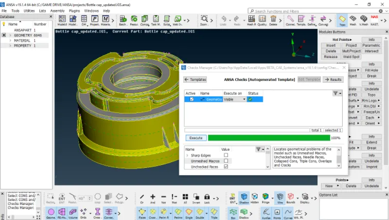
FIG 2: CLEANED UP GEOMETRY OF BOTTLE CAP.
- Measure Thickness on few edges and coons to generate the midsurface for the component.
- Set the Property IDs and Material IDs.
- Under the Mesh module change the set the Length of Perimeter and Macros to 1mm.
- Check visually for unorganised faces, delete it and create a new face with commands under Topo Module.
- Now go to Checks > Geometry.
- Select all the checkboxes except Sharp edges and Unmeshed macros and click execute.
- Errors like Triple cons , needle faces , cracked faces, single cons may appear.
- Select all errors , right click the mouse and select Autofix.
- Correct the errors by commands like hotpoints delete , insert , release.
- Commands like Faces > Delete , Topo, Orient Commands like Cons > Release , Project, Break
Generate Midsurface.
- The commands used for generating midsurface manually are faces > Offset because thickness can be easily measured for each part.
- First Generate Midsurface for larger parts and then go for features like ribs , threads.
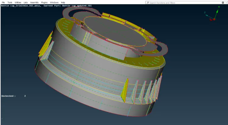
FIG 3 : MIDSURFACE MANUALLY EXTRACTED FOR THE BOTTLE CAP
- Use commands like Faces>Extend , Intersect, Set PID for features to get a proper mesh.
- Topo the faces properly after extraction.
Set the Quality Criteria.
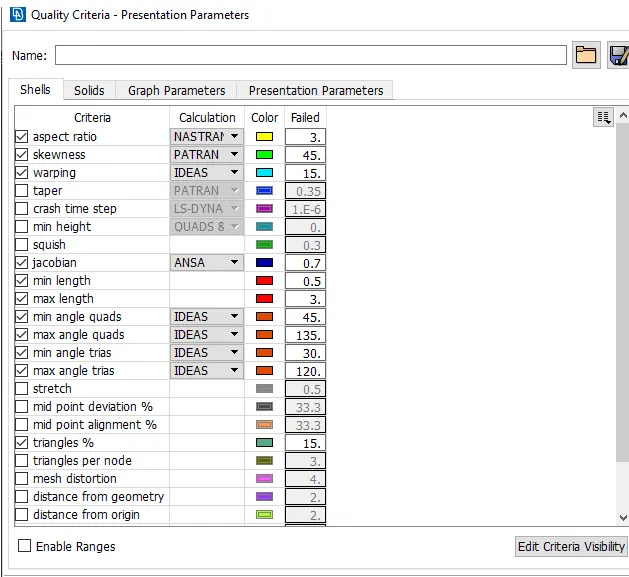
FIG 4 : QUALITY CRITERIA SETUP
Set the Mesh Parameters.
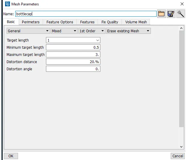
FIG 5 : MESH PARAMETERS UNDER BASIC TAB
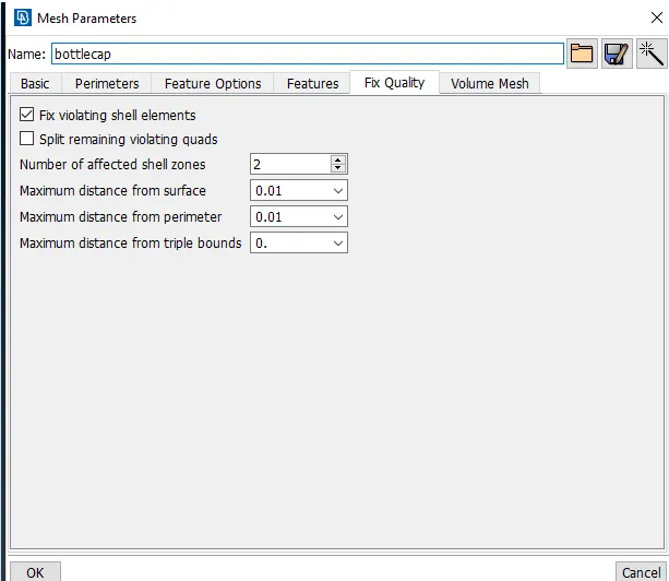
FIG 6 : MESH PARAMETERS UNDER FIX QUALITY TAB
Generating Mesh.
Select the Entire part and select the perimeter length to be at 1mm from the Mesh module.
- Use commands like Shell Mesh>Reconstruct, Smooth to get rid of errors.
- Use commands like Elements > Split, swap( to reorganise quad and tria elements).
- Use commands from Perimeter > Number , Num+/-
- Use commands like Macros > Cut , Join for reconstructing Mesh forms.
- Try to reduce the trias as much as possible and keep the quads in the majority of mesh to improve the quality of mesh.
- There must not be numbers mentioned in OFF under the shell quality card.
- Thus the meshing process is completed.
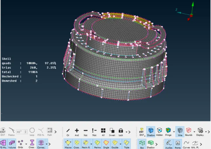
FIG 7 : GENERATED MESH IN SHADOW VIEW
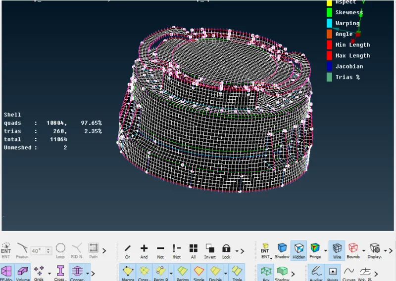
FIG 8 : GENERATED MESH IN HIDDEN VIEW UNDER SPECIFIED QUALITY CRITERIA
Assign Thickness to the mesh.
Go to Quality Criteria > Presentation Parameters and select the Draw Shell as Solid Check box. When switched to the Mesh Modules tab , The thickness can be viewed.
Release the entire meshed part for separating FE elements by using MESH module > Elements > release.
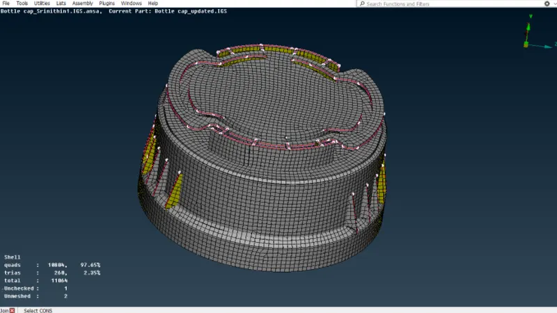
FIG 9 : MESHED BOTTLE CAP WITH THICKNESS
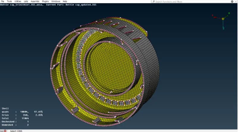
FIG 10 : MESHED BOTTLE CAP WITH THICKNESS
Result:
- A geometry clean up was performed.
- mid-surface was generated.
- The mid-surface was meshed as per the required quality parameters.
Learning outcomes:
Understood the challenges encountered when meshing a complex geometry.
Importance of defeaturing for attaining good quality.
Mid-surfacing regions with varied thickness.