Week - 4
- CONTROL LOGIC OF WASHING MACHINE
SEQUENCE:
If the power supply is available, the system gets activated.
If the water supply is not available, stop the process & indicate though LED.
Soakigntime should be 200s followed by wahsing time of 100s.
Rinsing happens for next 20s and dryer runs for 50s.
BLOCKS USED:
- Constant
- Toggle switch
- Rocker switch
- Chart / Stateflow
- Display
- Lamp / Indicator
INPUTS & OUTPUTS:
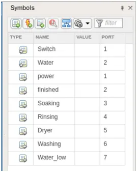
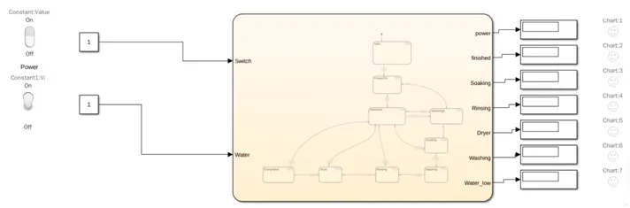
Switch input is provided from rocker switch for power supply
Water is provided from toggle switch indicates water supply
Power, Soaking, Rinsing, Dryer, Washing & Finished – output signal from stateflow when each state is commpleted
Water_low – output signal from stateflow to indicate the low level of water
MODEL:
The power to activate the system is given from constant thorugh rocker switch, when the switch is ON, input 1 is given to the stateflow and when the switch is OFF, input 0 is inputted to stateflow. The status of water is given through toggle switch. If the toggle switch is ON, the value is 1 and the water is FULL. If the toggle switch is OFF, the value is 0 and the water is LOW.
STATE FLOW:
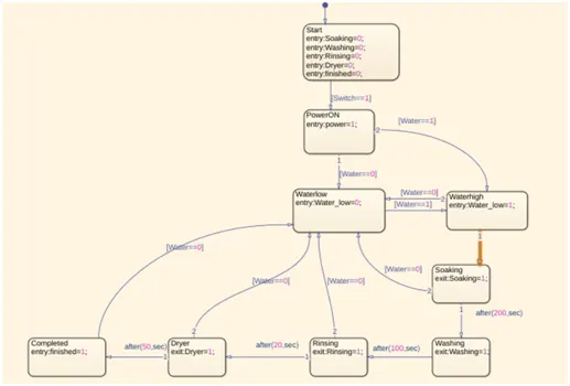
During the start of the stateflow, all the states are set to 0. If the rocker switch is ON, the flow moves to next state and set the output power value to 1. If the toggle switch is ON, the flow moves to next state and set the water_low signal as 0. Once the power and water supply is ON, the process starts with soaking, washing, rinsing and dryer at particular entioned time delay. If the water supply goes OFF, the water low signal is ON and the process stops.
- GEAR SHIFT LOGIC
|
Gear |
1 |
2 |
3 |
4 |
5 |
|
Speed (kmph) |
0 to 15 |
16 to 25 |
26 to 40 |
41 to 60 |
Above 61 |
BLOCKS USED:
- Slider gain
- Constant
- Chart / Stateflow
- Scope / Display
MODEL:
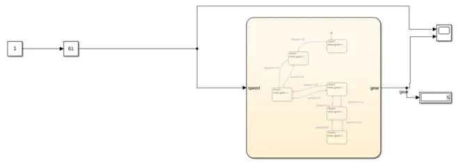
In the model, the speed input to stateflow model is given through constant block. To change the input during the runtime of the simulation, the slider gain block is used. The range is set as 0 to 100 in slider gain block. The gear shift logic is achieved by stateflow which is explained in next section. The output (gear) is observed using scope and display block.
STATE FLOW:
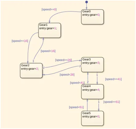
In stateflow, six states are created; Gear0, Gear1, Gear2, Gear3, Gear4, Gear5. During the start of the simulation time, the output parameter gear is set to 0 i.e., Gear0. Whenever the input parameter speed is greater than 0 and lesser than16 ,the output gear value is set to 1 i.e., Gear1. When the input parameter speed is greater than or equal to 16 & lesser than 26 ,then the output gear value is set to 2 i.e., Gear2. When the input parameter speed is greater than or equal to 26 & lesser than 41 ,then the output gear value is set to 3 i.e., Gear3. When the input parameter speed is greater than or equal to 41 & lesser than 61 ,then the output gear value is set to 4 i.e., Gear4. When the input speed value exceeds 61, the output gear value is set to 5 i.e., Gear5.
INPUT & OUTPUT:
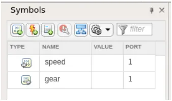
Speed is the input value from user. Gear is the output value in which gear number is assigned to.
SCOPE / DISPLAY:
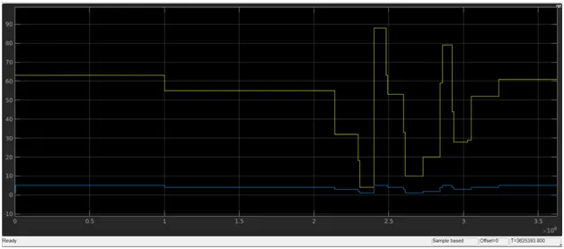
In the following figure, at t = 0to1 sec, the speed input is greater than 61 and the gear value is 5. At t = 1to2 sec, the speed input is between 50 and 60 & the gear value is 4 and so on.
Yellow – Slider gain
Blue - Gear