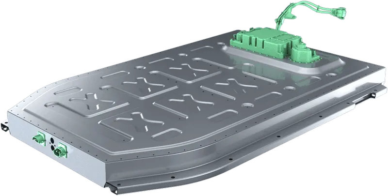
Project 1 Mechanical design of battery pack
Battery pack capacity: 18 kWh
Cell: ANR26650M1-B
Prepare a detailed battery pack drawing along with its enclosure. State your assumptions
ANR26650M1-B
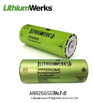
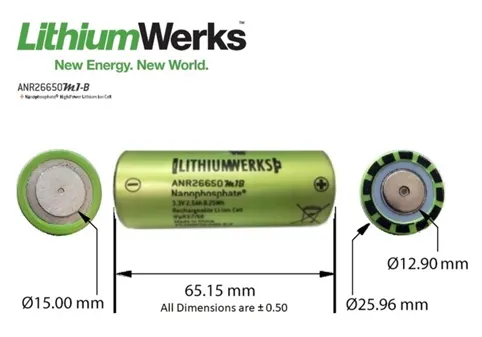
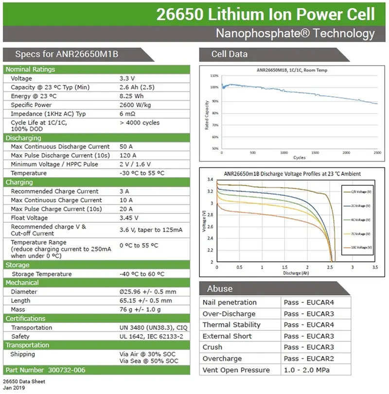
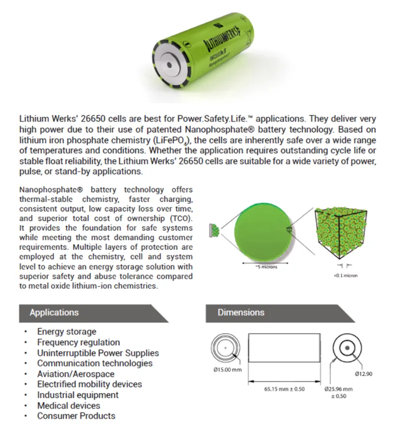
The specifications of ANR26650M1-B cell are listed as follows.
- Chemistry: Lithium Iron Phosphate (LiFePO4)
- Voltage: 3.3 V
- Capacity at 25 deg C: 2.56 Ah
- Energy at 25 deg C: 8.25 Wh
- Specific power: 2600 W/Kg
- Impedance (1Khz AC): >6 m-ohm
- Cycle life: >4000 cycles
- Cell type: 26650 Lithium ion power cylindrical cell
- Storage temperature: -40 deg C to 60 deg C
Discharge ratings:
- Maximum continuous discharge current: 50 A (20 C)
- Maximum pulse discharge current (10s): 120 A (48 C)
- Minimum voltage/ HPPC pulse: 2 V / 1.6 V
- Temperature: -30 deg C to 55 deg C
Charging ratings:
- Recommended charge current: 3 A
- Maximum continuous charge current: 10 A
- Maximum pulse charge current (10s): 20 A
- Float voltage: 3.45 V
- Recommended charge V & Cut-off current: 3.6 V, taper to 125 mA
- Temperature range (reduce charging current to 250mA when under 0 deg C): 0 deg C to 55 deg C
Dimensions
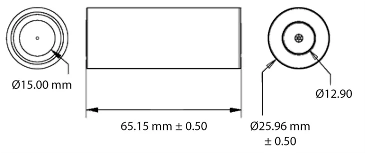
- Height (max): 65.15 (±5mm)
- Diameter (max): 25.96 (±5mm)
- Mass: 39.5 (±0g)
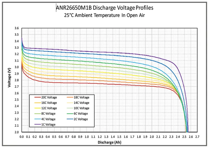
The following is the discharge characteristics of the ANR26650M1-B cell with different discharge rate.
CALCULATION:
Power of single cell P (Wh) = Voltage (V) x Current capacity (Ah)
= 3.3 V x 2.56 Ah
= 8.45 Wh
For calculation of battery pack here, we assume battery voltage is ~120 V
No. of cells connected in series = Battery pack voltage / Single cell voltage
= 120 / 3.3
= 36.36 ~ 40 cells in series
40 cells will be connected in series to achieve nominal voltage of ~120V
Energy capacity of a series line = No. of cells connected in series x Energy capacity of single cell
= 40 x 8.25 Wh
= 330Wh
No. of parallel lines connected = Energy capacity of battery pack / Energy capacity of series line
= 18000 / 330
= 54.5 ~ 55 parallel lines
So the battery pack configuration is 40S 55P and the specifications are as follows.
Battery Pack voltage = No. of cells connected in series x voltage of single cell
= 40 x 3.3 V
= 132 V
Capacity of the battery pack = No. of parallel lines x capacity of single cell
= 55 x 2.56 Ah
= 140.8 Ah
Battery pack total energy = total no. of cells in pack x Energy of single cell (Wh)
= 2200 x 8.25 Wh
= 18150 Wh = 18.2 kWh
Total number of cells in battery pack = No. of cells in series x No. of cells in parallel lines
Number of cells = 40 x 55 = 2200
Mass of battery pack = Total no. of cells in battery pack x Mass of single cell
= 2200 x 39.5 g
= 86.9 Kg ~ 87 Kg
Cell continuous current = C rate x Single cell capacity
= 10 x 2.56 Ah
= 25.6 A
Cell peak current = Max continuous C rate x Single cell capacity
= 20 C x 2.56 Ah
= 51.2 A
Battery pack continuous current = Cell continuous current x No. of parallel lines
= 25.6 x 55
= 1408 A
Battery pack peak current = Cell peak current x No. of parallel lines
= 51.2 A x 55
= 2816 A
Battery pack peak power = Battery pack peak current x battery pack voltage
= 2816 A x 132 V
= 371712 = 371.7 kW
Battery pack continuous power = Battery pack continuous current x battery pack voltage
= 1408 A x 132 V
= 185856 = 185.9 kW
Dimension of single cell:
BATTERY PACK ACCESSORIES:
Battery welding strip:
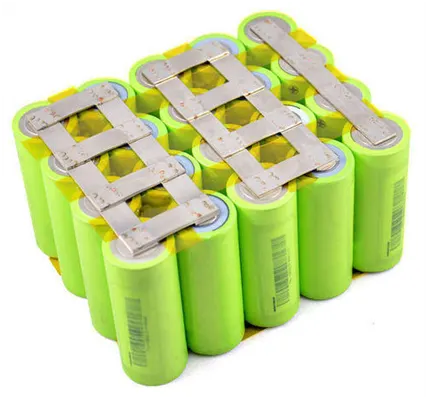

For the cells to be assembled in 40S 55P configuration, the cells are connected using nickel strip. Please find the above image for reference.
The cells are connected using nickel strip with excellent spot welding.
The specifications of Nickel plated steel shown above are as follows.
- Width 27mm
- Thickness 0.15mm
- Low resistance (15% lower than the traditional process)
- Corrosion resistance
Cell Holder:
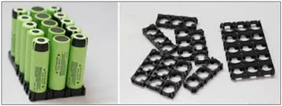
The battery holder is one or more compartments or chambers for holding a battery. A battery holder is either a plastic case with the shape of the housing moulded as a compartment or compartments that accepts a battery
Battery Management System (BMS):
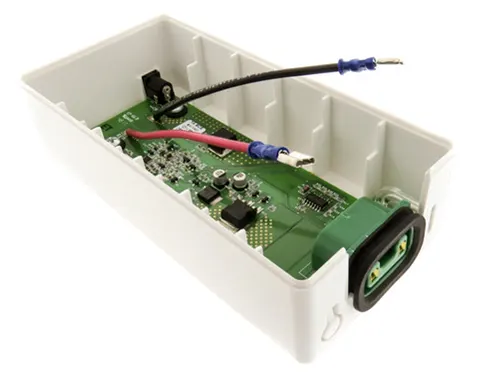
Battery Management system is electronic system that collects and stores the battery parameters like cell voltage, temperature, and remaining charge and computes the state of health, state of charge. A BMS also cuts off the battery from system if there is over-voltage, over-current and over-temperature.
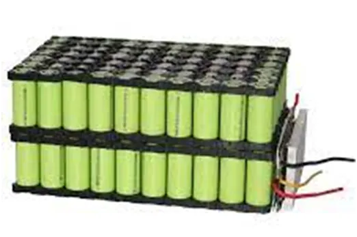
The BMS electronic system is mounted along the battery pack as shown below.
Battery Enclosure:
Battery pack is enclosed within box to provide ingress protection. The major two specifications to look while selecting enclosure is material and heat transfer. The enclosure material should be resistance to alkaline solution/Battery electrolyte and enclosure should be designed to have high heat transfer.
Aluminum is the less expensive and economical. it is light weight compared to equivalent steel enclosure design
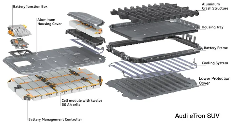
The final assembled battery pack would be similar to the following image