Week -2
- DOORBELL USING SOLENOID
Components used:
Pulse generator – to create signal high for 2 sec and low for 2 sec
Switch – which actuates when the physical signal is exceeds above 0.5 and switches ON the doorbell
Battery – as a DC voltage source to doorbell
Solenoid – which energizes when supply available and actuates the rod i.e. electromechanical block
Ideal translational motion sensor – to detect the movement the rod actuated by solenoid
Simulink Model:
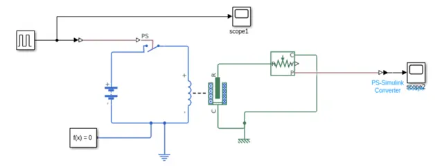
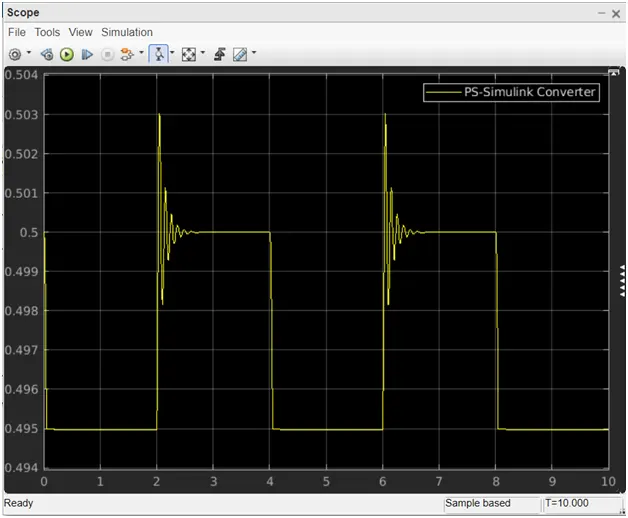
Pulse generator is used to create 2sec high and low signal. The simulink signal is converted into physical signal to actuate a switch. The switch completes the circuit from battery DC voltage source to solenoid. The Solenoid contains a coil which actuates the plunger when energized. The solenoid energizes for 2 seconds when the switch closes. The movement in the plunger is sensed by ideal translational motion sensor. The plunger is initially in 0.5m. Scope 1 show the output from pulse generator block and scope 2 shows the position output from ideal translational motion sensor.
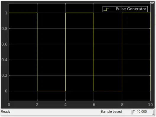
At t =0 to 2 sec, the pulse is high, switch closes, solenoid energizes and actuates the plunger. In scope 2, t=0 to 2 sec the plunger position changed from initial position.
At t=2 to 4 sec, the pulse is low, switch opens, solenoid de-energizes and plunger is back to initial position. In scope 2, t=2 to 4 sec the plunger position spring back to initial position.
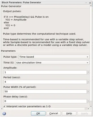
Pulse generator block:
Scope 1:
Scope 2:
- THERMISTOR TO SWITCH ON FAN
Components used:
- Signal builder – to generate signal to controlled temperature source
- Controlled Temperature Source
- Battery – as a DC voltage source to fan via thermistor
- Resistor – which acts as fan load
- Thermistor – Resistance varies according to temperature
- Voltage sensor – to measure the voltage across the fan load resistor
- Greater than (Logical)
Circuit:
Descrip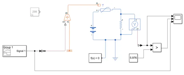 tion:
tion:
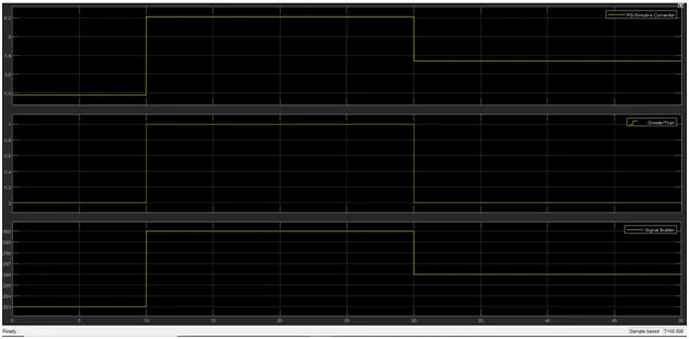
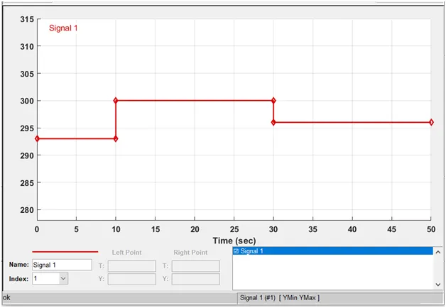
Signal builder generates signal as following
At t=0 to 10 sec, the signal will be 293
At t=10 to 30 sec, the signal will be 300
At t=30 to 50 sec, the signal will be 296
Based on the signal from the signal builder through port S, the controlled temperature source produces temperature. The Signal is the difference between the port A and B, port A is connected to temperature reference and so from port B the desired temperature is achieved. Thermistor is basically resistor whose resistance changes based on the temperature on port A of thermistor. The thermistor port + and – are connected to battery and resistor load. The voltage drop across the load resistor is calculated through voltage sensor.
At 298K (25degC), the voltage drop observed across the load resistor is 5.976V. As the temperature increases, the thermistor resistance decreases and allows more current flow which makes the voltage drop across load resistor higher. Therefore, whenever the voltage drop across load resistor increase beyond 5.976V, the fan will be switched ON by the signal from Logical greater than block.
Signal Builder:
Scope: