Project 2 Thermal modeling of battery pack
For a 10 cell series lithium ion battery model, simulate the thermal effects and compare life cycle performance at various temperatures, charge & discharge rates using MATLAB.
COMPONENTS USED:
- Battery (table based)
- Temperature sensor
- Convective heat transfer
- Thermal source
- Voltage sensor
- Current sensor
- Solver configuration
- Gain
- Integrator
- Thermal reference
- Electrical reference
- Scope
DESCRIPTION:
Battery (Table based):
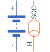
Battery – table based is the model with high accuracy compared to the simulink battery model. Select the Instrumented | show thermal port option. This option allows the user to output the state of charge of the battery and input the temperature.
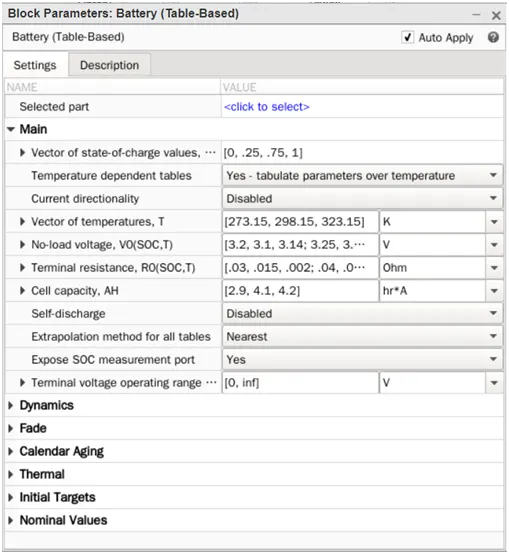
Temperature sensor:
Temperature sensor got two input ports A& B and output port T. The output port T gives the difference of temperature between the two input ports. Connect the port A of sensor to the battery temperature to measure temperature applied on the battery.
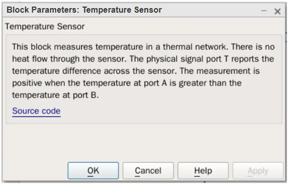
Convective heat transfer:
The model gives the effect of heat transfer by convection through fluid motion. The rate of heat transfer is proportional to the heat transfer co-efficient and surface area contact with the fluid.
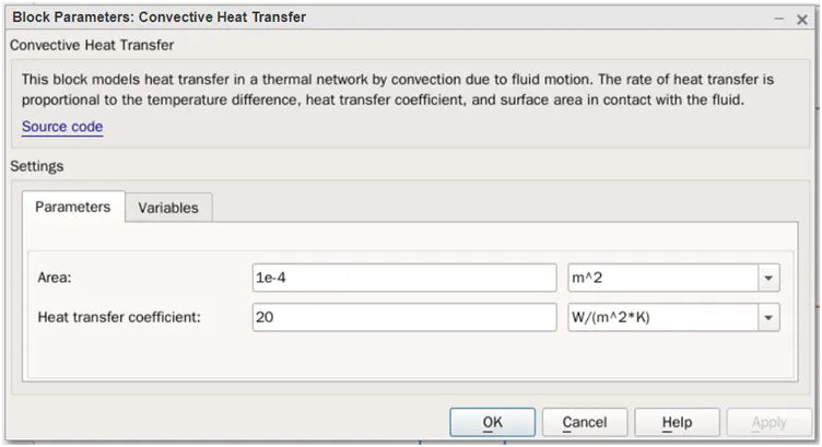
The surface area in contact can be modified by changing the values in the block parameters. For different contact area, the battery discharge characteristics are plotted.
Thermal Source:
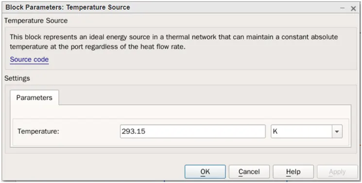
Thermal source model gives constant temperature of 293.15 Kelvin. The temperature is modified to 300K and 320K to analyze the battery pack performance at various temperature, charging and discharging rate.
Voltage Sensor:

Voltage sensor has two electrical terminals and one output (physical signal). The potential difference between the terminal A and B are computed and provided in output in form of physical signal. The voltage sensor must be connected in parallel to the load/terminals to be measured.
Current Sensor:
Current sensor has two input terminals and one output (physical signal). The current passing through the terminal A and B are measured and given in output in form of physical signal. The current sensor must be connected in series to the load to measure the current flowing through it.
MODEL:
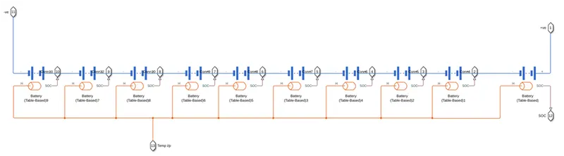
The 10 numbers of battery (table based) are connected in series. The voltage of single battery cell is 3.59 Volt, since 10 cells are connected in series, the battery pack voltage is 3.59*10 ~ 35.9 V. The temperature input for the battery pack is provided from temperature source through convective heat transfer. All the cells in the battery pack are provided with same temperature input. The battery cells are combined to form a subsystem called battery pack. The subsystem contains two power terminals i.e., battery pack positive (1) and battery pack negative (11) and a temperature input signal (13) and 10 output signal (2 to 10 & 12) - SOC from each battery cell.
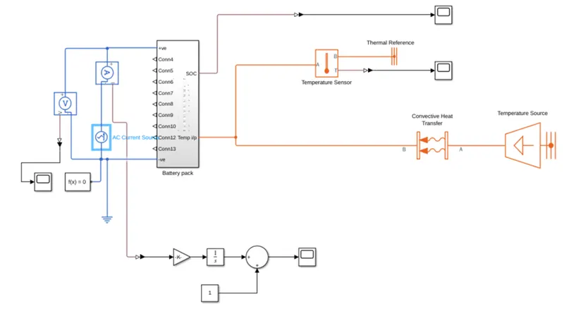
The battery pack is charged and discharged continuously using AC current source. The AC current source is connected to battery pack power terminals to simulate the charge-discharge cycle. To measure the battery pack voltage, the voltage sensor is connected across the power terminal of battery pack. To compute the state of charge of the battery pack, the current entering/leaving the battery pack is measured continuously using current sensor.
The temperature input to the battery pack is given by temperature source through convective heat transfer. The temperature signal inputted for battery pack is measured by temperature sensor. The temperature source holds the ambient temperature. By changing the ambient temperature, the battery pack discharging cycles are recorded and analyzed in results.
Battery pack voltage, Temperature input to battery and SOC are connected to the block scope to record the data and analyze.
RESULT:
The voltage of the battery pack is observed, and the curve is attached below.
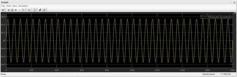
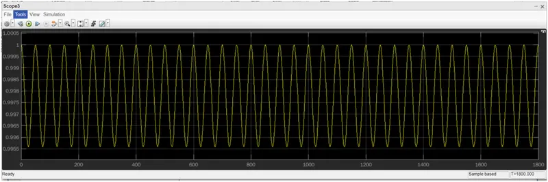
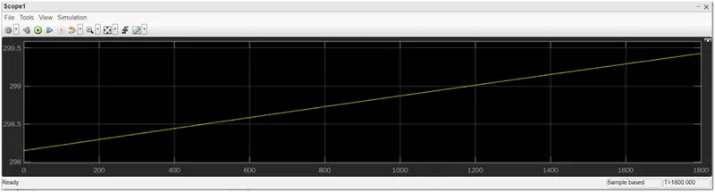
Case 1, 2 & 3 – All the three cases are observed the battery pack performance in different temperature when the pack is continuously charging and discharging at 1C rate.
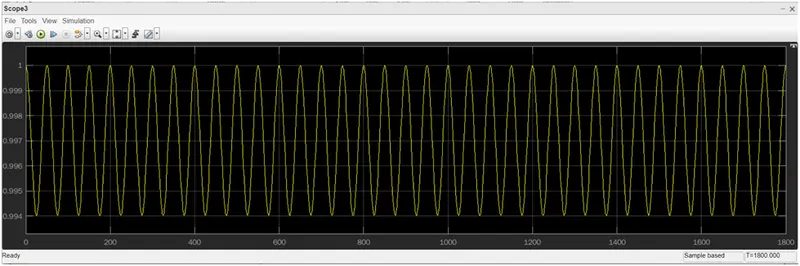
Case 1: 293.15 K
SOC:
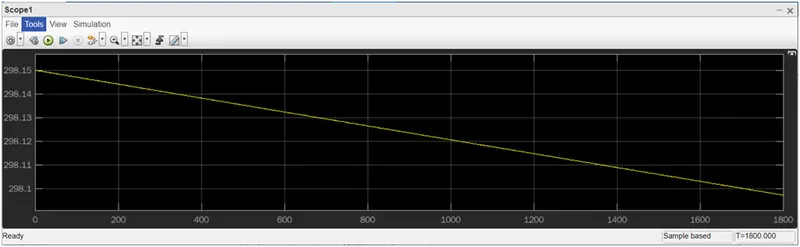
Temperature input:
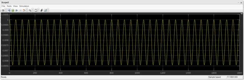
Case 2: 300 K
SOC:
Temperature input:
Case 3: 320 K
SOC:
Temperature input:
Battery pack characteristics at 0.5C rate of charging and discharging
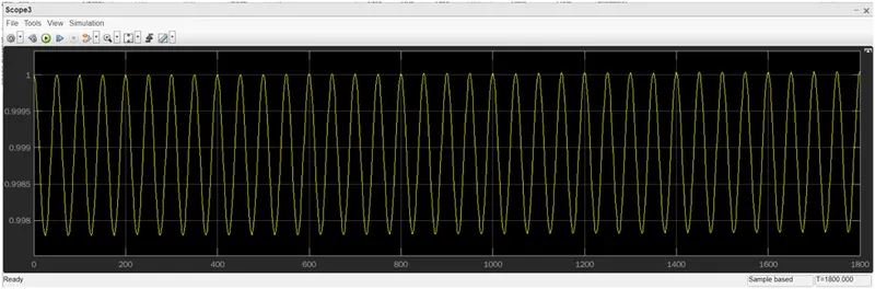
Battery pack characteristics/performance at 0.2C rate of charging and discharging
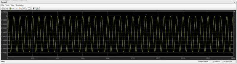
Battery pack characteristics/performance at 2 C rate of charging and discharging 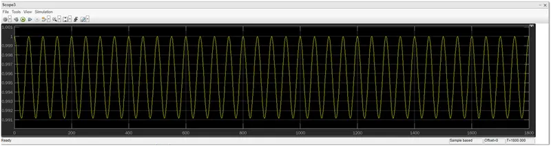
INFERENCE:
When the charging/discharging rate is greater than 1C, the performance and capacity of the battery pack is degraded.
when the ambient temperature of the battery pack changes, it will have an effect on the usable capacity of the battery pack and degrades the performance of the cell.